

Version: V2.6 Final Edition, July 2026.
Compilation note: This book is compiled from the technical content system of the RealMeter Leak Research Institute. Parts I–III cover industry-generic knowledge (physics, metrology, methodology); Part IV presents RealMeter's technical solutions. All RealMeter product parameters are cited from the 2026 RealMeter® Calibrated Leak Product Handbook & Configuration Guide (Revised Edition) and publicly released materials.
Disclaimer: This book is for technical exchange and training only and does not constitute an acceptance basis; acceptance shall follow the certificates and contract conditions confirmed by both parties. Please credit the source when citing.
The calibrated leak is a "small but weighty" industry: the device is the size of a thumb, yet it carries the pass/fail judgment of the entire manufacturing world. For decades, the knowledge of this industry has been scattered across metrology specifications, vacuum textbooks, leak-detector manuals and the experience of veteran engineers — no book has ever strung together a complete path "from entry level to deep understanding." This book attempts to fill that gap.
Structure: Part I (Cognition, Ch. 1–3) builds the language and the physics: what leak rate is, how units convert, and what happens inside a leak. Part II (Principles, Ch. 4–7) builds judgment: the process spectrum, lifetime physics, valves and dead volume, uncertainty and traceability. Part III (Applications, Ch. 8–12) builds methodology: leak-test methods, quantitative semiconductor RGA, system-level air-tightness accuracy, the helium-reduction paradigm, selection and FAQ. Part IV (Solutions, Ch. 13–16) presents one answer: what emerges when this knowledge system is fully engineered. The appendices provide quick-reference tools.
How to use this book: New engineers should read sequentially from Chapter 1 — the first three chapters will give you a more solid foundation than most three-year practitioners. Production process and quality engineers may jump to Chapters 8–12: the Four-Piece Kit, the bypass method and Three-Reference helium reduction are usable tomorrow. Metrology and audit personnel: Chapter 7 and Appendix D are written for you. Procurement and decision-makers: the "rules" and "four questions" in Chapters 4, 11 and 12 can be written directly into tender documents.
One promise: For every physical conclusion, we show the derivation; for every product parameter, we cite the source; for every capability boundary, we state it honestly (including what we ourselves cannot do). We believe this is the only way a white paper earns trust.
On production lines for power batteries, automotive air conditioning, semiconductors and medical devices, thousands of such judgments are made every second: does this part leak or not? OK — release; NG — reject. The judgment is made by a leak detector: a helium mass-spectrometer leak detector, a differential-pressure air-tightness tester, or a halogen leak detector. But the detector itself cannot "know" how large a leak counts as rejectable — it is merely an instrument that amplifies a gas signal into a number. What truly answers "how big counts as leaking" is a thumb-sized device: the calibrated leak.
Its role is exactly that of a weight on a balance, or of a standard voltage source when calibrating a multimeter: the instrument gives a reading, the standard tells whether the reading is trustworthy. The leak detector is the scale; the calibrated leak is the weight. If the weight is wrong, the more precise the scale, the more confidently it errs. The two costliest quality accidents on a production line — false rejects (good parts scrapped) and missed rejects (defective parts shipped) — when traced to the end, point in a remarkable proportion of cases to the same root cause: the yardstick itself is untrustworthy, or its working conditions were not used correctly.
A calibrated leak is a reference device that provides a known and stable leak rate under specified working conditions (gas species, inlet pressure, outlet pressure, temperature), calibrated and certified by a metrological institution. The Chinese national metrology specification JJF 1833—2020, Calibration Specification for Vacuum Helium Leaks, defines a vacuum helium leak as "an element that provides a known helium flow rate, used to calibrate the sensitivity of helium mass-spectrometer leak detectors," and divides leaks by structure into two classes: channel-type leaks (the leak element is a real geometric channel, e.g. capillary, orifice, crushed-metal) and permeation leaks (with quartz glass or similar as the permeation element)[1].
The definition contains three indispensable keywords — they form the essential difference between a "standard source" and an arbitrary pinhole:
| Element | Meaning | Counter-example (what a random hole does) |
|---|---|---|
| Repeatable | Same output today, tomorrow and next year under identical conditions — even after temperature swings, vibration and shipping | Channel drifts with temperature and creeps over time; readings differ month to month |
| Traceable | The leak-rate value is traceable through an unbroken calibration chain to the national primary standard, with known uncertainty at every link | The rate is merely "the vendor's rough figure," unprovable |
| Verifiable | A certificate states the calibration conditions and uncertainty; a third party can re-verify to the same specification | No certificate, or a certificate without stated conditions — nothing to check against |
These three elements are also the undercurrent of the whole book: every later chapter — flow-regime physics (Ch. 3), the process spectrum (Ch. 4), lifetime physics (Ch. 5), uncertainty (Ch. 7) — is essentially answering "how to push the three elements to their limits."
The calibrated leak sits in the exact middle of a complete chain of trust. Upstream lies metrology; downstream lies product quality:
The calibrated leak therefore has a property rarely seen in other measuring instruments: its error is amplified twice — first copied into the detector's systematic error, then copied into every product judgment. A calibrated leak with a +20% rate deviation, unknown to its user, keeps an entire production line running day and night against a wrong threshold. This is why metrology specifications impose hard requirements on the annual stability of calibrated leaks (JJF 1833—2020 requires ≤ 3%/year) and on calibration-facility uncertainty (relative expanded uncertainty better than 10%, k = 2)[1] — and why this book devotes a full chapter each to "decay" and to "uncertainty."
Three concepts are constantly conflated in the field and must be separated:
| Concept | Definition | Key point |
|---|---|---|
| Calibrated leak | A deliberately manufactured, metrologically calibrated standard source | An intentional "good leak" — the more stable, the more valuable |
| Leak point | An objectively existing defect channel on the workpiece (crack, weld porosity, sealing-face notch) | Almost never a round hole; often not reproducible |
| Equivalent channel | The leak point's gas-transport capability at a given pressure difference and gas, expressed as that of a geometric channel | The only engineerable object that can be compared and calibrated |
The key insight: leak testing measures "leak rate," never "orifice diameter." A 50 μm crack and a 5 mm capillary are, for sealing purposes, the same problem as long as they transport gas equally under the same conditions. A calibrated leak provides precisely such a stable, controllable, reproducible equivalent leak channel — used to "impersonate" the critical defect on the workpiece (the OK / NG judgment and helium-reduction systems of Ch. 10–11 are built on this). Every conversion of "what hole diameter does this leak correspond to" is meaningless without specifying gas species, pressure and flow regime (Ch. 3 gives a rigorous treatment).
How does the leak-rate value reach your production line, step by step? The figure below shows the complete chain:

Every link has a name: the primary leak-rate standard maintained by the National Institute of Metrology (NIM) → calibration facilities at metrology institutes at various levels (JJF 1833—2020: flow-meter / fixed-quantity gas facilities must have relative expanded uncertainty better than 10%, k = 2; comparison facilities better than 20%)[1] → reference calibrated leaks (master standards used by institutes to establish their standards, each with a national-level certificate) → working calibrated leaks (for daily line checks and detector calibration) → detector readings → product OK / NG judgment.
This chain explains two phenomena familiar in the industry:
The calibrated leak is not a single product but a multi-dimensional family. Master the following six classification dimensions and you hold the "map coordinates" of this book:
| Dimension | Categories | Physical / engineering significance |
|---|---|---|
| ① Structural principle | Channel-type (capillary, orifice, crushed, microchannel) / permeation (quartz membrane, etc.) | Determines tempco, pressure rating, media compatibility (Ch. 3, 4) |
| ② Gas supply | Reservoir-type (built-in gas volume) / passive (external supply) | Reservoir leaks work standalone but decay (§3.8); passive leaks never decay and can simulate any condition |
| ③ Outlet condition | Vacuum leak (into vacuum) / positive-pressure leak (into atmosphere) | One leak, two ratings; §2.5 gives the conversion conditions |
| ④ Medium | Single gas / gas mixture / isotopes / liquids (water, dodecane, DMC, etc.) | Gases follow conductance models; liquids follow evaporation–transport models (Ch. 3 & 6) |
| ⑤ Test method | He-MS / differential-pressure / hydrogen / halogen-refrigerant / RGA / MFC micro-flow | Each method imposes different requirements on the leak (Ch. 8) |
| ⑥ Form factor | Reservoir / probe / micro-size (down to Φ2.0 mm class) / built-in / adjustable | Form serves installation space and in-situ calibration (Ch. 14) |
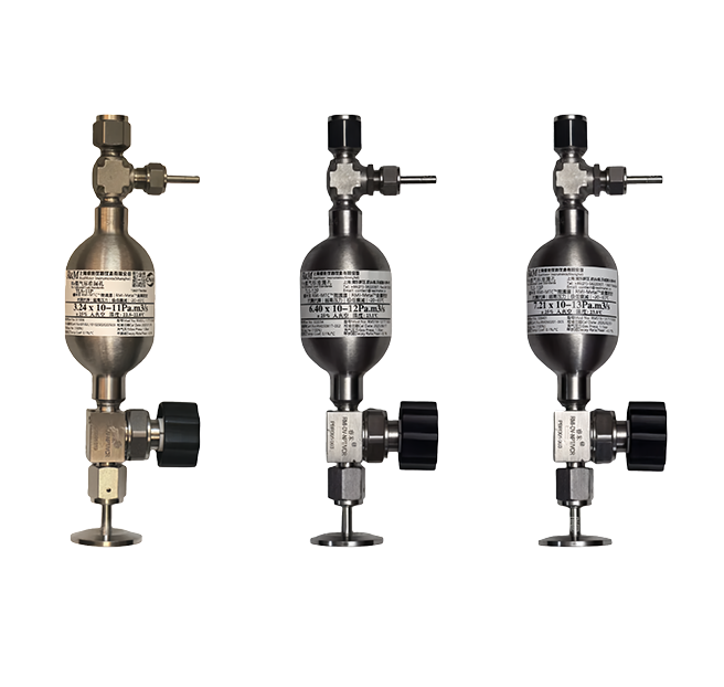
Reservoir vs passive is the first choice to make in the field, so build the intuition early: a reservoir-type leak is like a "self-inking standard stamp" — open the valve and it works; portable, independent, ideal for detector calibration and metrological traceability. A passive leak is like a "standardized precision capillary" — driven by the local gas supply, it can precisely simulate workpiece leakage at any pressure, and is the foundation of OK / NG judgment systems and helium-reduction schemes (Ch. 10, 11). Neither is better; they simply have different applicable boundaries.
Over the past decade, four industry-level changes have pushed the calibrated leak from "accessory of the leak detector" to "foundation of the quality system":
| Driver | Change in testing demand | Requirement on leaks |
|---|---|---|
| Mass production of EV batteries | High-takt He / H₂ testing of cases and cooling systems | Shock resistance, high-frequency checks, OK/NG three-piece simulation sets, helium reduction |
| Structural helium shortage | Pure He → low-concentration He (1% ~ 50%) | Three-Reference simulation references that stay decidable at low concentration (Ch. 11) |
| Semiconductor & UHV | RGA quantification, isotope / mixture calibration | Zero-dead-volume valves, all-metal sealing, ultra-low background (Ch. 6) |
| Maturing metrology system | JJF 1833—2020, JJG (military) 165—2024 and others in force[1][2] | Reference-grade leak sets, uncertainty budgets, standardized certificates |
The next chapter settles the most fundamental — and most error-prone — language problem of this industry: the units and magnitudes of leak rate.
Leak rate is neither hole size nor gas volume, but the product of pressure and volume transported through the leak channel per unit time:
Q — leak rate; pV — the pressure × volume product of the transported gas (a measure of "amount of gas"). Under isothermal conditions, pV is proportional to the number of molecules, so leak rate is essentially "how many molecules pass per unit time."
Why not use volume flow directly? Because gas is compressible: 0.01 cm³/s on the high-pressure side may expand to 10 L/s on the low-pressure side. Only pV is invariant along the path (at constant temperature) — this is why vacuum technology worldwide uses "pressure × volume / time" as the base dimension of leak rate. All the units below are merely different pV conventions.
| Unit | Equal to 1 Pa·m³/s × | Main user communities |
|---|---|---|
| Pa·m³/s | 1 | SI; Chinese national standards; vacuum community |
| mbar·L/s | 10 | European leak-detector convention; vacuum industry daily unit |
| atm·cc/s | 9.87 | American convention; semiconductor & hermetic-package community |
| Torr·L/s | 7.50 | Vacuum engineering (older literature) |
| sccm (std. cc/min) | 592 | Gas flow, MFC community |
| g/y (grams per year) | medium-dependent | Refrigeration & automotive A/C regulations |
The three most useful relations to memorize:
g/y is a special dialect: it is a mass flow, whose conversion to pV flow depends on the molar mass of the medium:
m — molar mass (g/mol); t — temperature (°C); 22.413 L/mol is the standard molar volume; the 273/(273+t) factor corrects the volume from t °C to 0 °C; 1.013 converts mbar to atm. For R134a (m = 102 g/mol): 1 mbar·L/s ≈ 1.3×10⁵ g/y, i.e. 1 g/y ≈ 7.6×10⁻⁶ mbar·L/s — thus the "a few grams per year" regulatory language of the refrigeration industry connects with the "10⁻⁵ ~ 10⁻⁶ class" technical language of the vacuum industry.
Numbers alone build no intuition; time does. How long does a leak of a given rate take to leak one standard cubic centimeter (1 std.cc ≈ 1 mL of gas at 0 °C, 1 atm)?
| Leak rate / mbar·L/s | Time for 1 std.cc | Typical scenario |
|---|---|---|
| 10⁻² ~ 10⁻³ | ~100 s ~ 17 min | Coarse air-tightness check, large-flow MFC calibration |
| 10⁻⁴ ~ 10⁻⁵ | 2.8 h ~ 1.16 days | Battery cases, A/C lines — the industrial main battlefield |
| 10⁻⁵ ~ 10⁻⁶ | 1.16 ~ 11.6 days | High-sealing relays, compressor assemblies |
| 10⁻⁷ ~ 10⁻⁸ | 116 days ~ 3.2 years | Hermetic packages, sensor cavities |
| 10⁻⁹ ~ 10⁻¹⁰ | 3.2 ~ 32 years | UHV devices, space components |
| 10⁻¹¹ ~ 10⁻¹³ | 320 years ~ 320,000 years | Metrology class: reference calibrated leaks, extreme-sealing verification |

Three intuitions to carry away: ① each order of magnitude is a tenfold world — the difference between 10⁻⁵ and 10⁻⁶ is not 10%, but ten times the time; ② everyday language is misleading — a "slight leak" of 10⁻³ is a hundred billion times a "metrology-class leak" of 10⁻¹³; ③ small leaks do not mean small risk: a 3.5×10⁻⁶ mbar·L/s hydrogen calibrated leak releases only ~0.3 mL of hydrogen per day, far below any combustion-concern threshold — magnitudes must be discussed together with gas species and environment.
Two pairs of conditions on a certificate change the numerical value of the "same" leak; they are the most frequent sources of field disputes.
First pair: vacuum outlet vs atmosphere outlet. The same channel into vacuum (outlet ≈ 0) vs into atmosphere (outlet ≈ 1 atm) gives different rates — in molecular flow the difference is small (rate ∝ Δp: 11 bar vs 10 bar, about 10%); in viscous flow it can be large (rate ∝ p₁² − p₂²: 11² − 1² vs 11² − 0, about 0.8% at 11 bar, but 25% at 2 bar). Certificates must state the outlet condition; between the two ratings, use the flow-regime formulas of Chapter 3 to convert, never "approximately the same."
Second pair: gauge vs absolute pressure. Field pressure gauges read gauge pressure; physical formulas use absolute pressure. A part tested at 20 kPa gauge is at ~121 kPa absolute; a 1% error in absolute pressure terms is not 0.2 kPa but 1.2 kPa. All calculations in this book use absolute pressure; all field settings must add one atmosphere (~101.3 kPa) before use.
The MFC and calibration communities distinguish "standard-state volume flow" (sccm: volume per minute reduced to 0 °C, 1 atm) from "actual volume flow" (ccm: at actual temperature and pressure). They differ by the temperature/pressure correction factor: 1 ccm measured at 23 °C equals ~0.92 sccm. Certificate conversions and calibration-system settings must state the reference temperature — the default in this book is 0 °C (273.15 K), and 23 °C measurements are explicitly marked when used.
Misconception 1: treating mbar·L/s as "hole diameter." The same 10⁻⁵ mbar·L/s may correspond to completely different physical channels for different gases, pressures and structures — leak rate is a transport capability, not a geometric size (§1.4).
Misconception 2: converting between gases with one fixed factor. The truth: in molecular flow Q(He) ≈ 2.65 × Q(air) (light molecules leak faster, the 1/√M law of Eq. 3-3), while in viscous flow Q(air) ≈ 1.06 × Q(He) (inverse viscosity ratio, Eq. 3-2) — the two factors, 2.65 and 0.94 (= 1/1.06), differ by nearly a factor of three and point in opposite directions. Gas-conversion factors depend on the flow regime, which depends on pressure and orifice size — see §3.6; this is the most underestimated pit in the industry.
Misconception 3: comparing certificate values without conditions. Two certificates both saying "1×10⁻⁵ mbar·L/s" may differ by tens of percent in actual behavior if one is vacuum-outlet He and the other atmosphere-outlet N₂ — the four conditions (gas, inlet pressure, outlet, temperature) must be aligned before comparison (Rule 2-1).
With the language in place, the next chapter opens the leak itself: what determines its output — the three flow regimes, and the temperature effects that quietly rewrite the numbers.
Gas flowing through a microchannel exhibits three completely different personalities, depending on the ratio of the molecular mean free path λ (the average distance a molecule travels between collisions) to the characteristic channel size d — the Knudsen number Kn = λ / d:
Concrete feel: for a leak with d = 5 μm at 1 atm inlet, Kn ≈ 0.014 (viscous side); pump the inlet down to 100 Pa and λ grows a thousandfold, Kn ≈ 13 (molecular side). The same physical leak may switch flow regimes as operating pressure changes — this is the physical root of "numbers that don't match" when rating conditions differ (echoing Rule 2-1). For extremely fine channels of 50 nm, the flow is already molecular even near atmospheric pressure.
d — channel diameter; L — length; η — gas viscosity; p₁, p₂ — inlet / outlet absolute pressures.
Three engineering corollaries: ① d⁴ sensitivity — a 1% change in diameter shifts the rate by 4%; this is the fundamental difficulty of making stable leaks, and the reason metal-crushed and drawn-glass processes struggle with consistency; ② rate depends on the pressure difference of squares — doubling inlet pressure nearly quadruples the rate, which is why rating pressure must be pinned down; ③ rate is inversely proportional to viscosity η — for the same channel, gases with higher viscosity (air 18.5 μPa·s) leak slower than lower-viscosity hydrogen (8.9 μPa·s), and helium (19.6 μPa·s) leaks slowest of the three.
v̄ — mean molecular thermal speed; M — molar mass; T — absolute temperature.
Key corollary: in molecular flow the rate is inversely proportional to √M — for the same channel, the smaller the molecular mass, the faster the leak. He (M = 4) vs N₂ (M = 28): the molecular-flow rate ratio is √(28/4) ≈ 2.65. This is the physical reason helium is the premier tracer gas: for the same defect, the helium signal is 2.65 times the air signal (and its background in air is only 5.2 ppm, so the signal-to-noise ratio is overwhelming). Note the d³ scaling here (vs d⁴ in viscous flow): geometry matters differently across regimes — the basis of the "process yardsticks" in Chapter 4.
Z(Kn) — a transition correction factor (empirical form, e.g. the Knudsen interpolation); in engineering it is often sufficient to add the two components directly and validate against measurement.

The danger of the transitional region: the apparent "pressure exponent" drifts between 1 and 2, and gas-conversion factors lie between the viscous and molecular limits without a universal value. Whenever you see "rate vs pressure is neither linear nor quadratic," you are in the transitional region — at that point, only a full-range calibrated leak, or a computational model validated by full-range data, can give trustworthy ratings. RealMeter's RMI-Cal™ conductance-simulation engine is built on precisely this class of models (Ch. 13).
Temperature is the invisible hand that rewrites leak rates daily. The three structural families behave completely differently:
| Family | Dominant mechanism | Typical tempco | Engineering consequence |
|---|---|---|---|
| Channel-type (molecular flow) | Molecular thermal speed v̄ ∝ √T | ≈ +0.17 %/°C (theoretical, Eq. 3-5) | Nearly negligible in general industry |
| Channel-type (viscous flow) | Gas viscosity η rises with T | ≈ −0.24 ~ −0.6 %/°C | Matters in precision calibration |
| Permeation (quartz membrane) | Arrhenius permeation activation | ≈ +3 ~ +4 %/°C | 5 °C swing = 20% drift; temperature control mandatory |
Eq. (3-6) is the theoretical lower bound for viscous flow; with structural corrections, real metal-channel leaks measure about −0.6 %/°C. Eq. (3-7) is the Arrhenius form for permeation: Ea — activation energy.
The engineering conclusion writes itself: temperature coefficient is the sharpest single indicator separating leak technologies. A production floor without climate control swings ±5 °C day and night: a permeation leak drifts ±20%, while a metal-channel leak drifts less than ±1% (viscous) or ±0.85% (molecular) — whether a daily OK / NG judgment needs temperature compensation depends entirely on this number. This is why the selection chapter (Ch. 12) makes "tempco ≤ 0.2 %/°C" a hard threshold for line duty.
The rigorous answer to Misconception 2 of §2.6 — rate ratios between gases for the same channel (using He→N₂ and He→H₂ as examples):
| Conversion | Molecular flow (1/√M) | Viscous flow (η ratio) | Note |
|---|---|---|---|
| He → N₂ (air) | × 0.38 (÷ 2.65) | × 1.06 | Directions opposite; transitional region in between |
| He → H₂ | × 0.71 (÷ 1.41) | × 2.2 | Hydrogen testing needs regime confirmation even more |
Water, dodecane, DMC and other liquid-media "leaks" do not flow — the liquid evaporates at the channel inlet, vapor is transported along the channel, and condenses at the outlet. The rate depends on saturated vapor pressure and channel conductance, and is far more temperature-sensitive (the vapor-pressure curve is steep): dodecane runs ~12 %/°C, so a ±0.5 °C temperature-control error alone means ~6% rate drift. Such leaks are mainly used for liquid-cooling-plate and refrigerant-circuit simulation; Ch. 6 (§6.5) and Ch. 9 (§9.5) discuss their rating and use.
A reservoir-type (self-contained) leak is a small gas tank leaking through a calibrated channel: as gas leaves, pressure falls, and the rate falls with it — this is "decay," not a fault but an inherent property. With initial rate Q₀, reservoir pressure p and volume V:

Reading the figure: ① 11 MPa / 300 cc — only 22.3% decay in ten years; ② 11 MPa / 160 cc — 35.0% in ten years; ③ 1 MPa / 160 cc (ordinary charge) — 70.3% gone in just four years. Decay is not destiny; it is design (the day-by-day iteration behind this figure is equivalent to the closed-form solutions of Eqs. 3-9 / 3-10): high-pressure charging and enlarged volume push annual decay below 3%, satisfying the JJF 1833—2020 stability requirement; low-pressure small-volume products are disqualified at birth. When choosing a reservoir leak, ask for the decay-curve calculation before the certificate (Ch. 12).
With physics in hand, Part II uses this yardstick to measure every process route in the industry: who can make stable channels, and who cannot.
Chapter 3 told us that a leak's macroscopic behavior is governed by four physical quantities. To judge any process, simply ask how well it controls these four:
| Yardstick | Formula origin | Corresponding engineering metric |
|---|---|---|
| Orifice d (and its consistency) | Eq. (3-2): Q ∝ d⁴; Eq. (3-3): Q ∝ d³ | Rate tolerance, batch consistency, customizability |
| Channel regularity | Ideal circular-tube assumption | Directionality, clog resistance, computability |
| Material & seal background | Permeation, adsorption, outgassing | Minimum achievable rate, media purity, tempco |
| Structural strength | Pressure, shock, thermal cycling | Pressure rating, drop resistance, temperature range, lifetime |
The orifice item deserves quantification. From Q ∝ d⁴, the relation between rate tolerance and orifice tolerance:
For a 5 μm orifice, ±2.4% means diameter control within ±120 nm. Leak manufacturing is, at its core, a contest of sub-micron geometric control — every process difference below ultimately lands on this point.
Principle: a glass tube is fused with a metal wire (or glass rod) and drawn thin; the micro-gap formed by the differential thermal expansion of glass and metal on cooling serves as the leak channel. Capability: typical rates 10⁻⁴ ~ 10⁻⁷ mbar·L/s, pressure generally < 1 MPa. Failure modes: first, the gap is an annular taper rather than a circular tube — orifice varies along the axis, forward and reverse conductance differ, i.e. the rate is directional (§4.9, §5.4); second, glass brittleness means it fears drops, freezing and pressure shocks, with short field life; third, the gap geometry is not designable — target rates are achieved by "draw a batch, measure a batch, pick a few," with consistency left to luck.
Principle: a fine metal tube (or metal foil sandwiching a wire) is repeatedly crushed, measured, crushed again, until the rate falls into the target band. Capability: typical rates 10⁻¹ ~ 10⁻⁶ mbar·L/s, pressure generally < 2 MPa. Failure modes: the crushed channel is a crescent-section product of trial and error — directional as well; metal creeps slowly under stress, so the rate drifts over time; die wear translates directly into batch variation. Its merits are low cost and large rates, so it survives in coarse testing — but "adjustable, computable, reproducible" is out of the question.
Principle: small molecules such as He undergo a "dissolve–diffuse–desorb" permeation through quartz glass; the rate is set by membrane area and thickness. Capability: can reach 10⁻⁹ ~ 10⁻¹² class — long the mainstream choice for built-in calibration leaks of helium detectors. Failure modes: first, tempco as high as ~ +4 %/°C (the Arrhenius mechanism of Eq. 3-7): a 5 °C workshop swing means ~20% drift, so a temperature-correction table is mandatory; second, the differential pressure across the membrane is limited (the membrane is the weak point) and glass is brittle; third, the medium is locked — only small molecules like He and H₂ permeate; N₂, Ar, refrigerants and mixtures are all excluded; fourth, quartz permeation of He is itself a ~10⁻¹⁰ atm·cc/s "background" — going smaller means drowning in your own background (§5.2).
Principle: metal or ceramic powder is sintered into a porous body; conductance comes from the statistical average of a vast number of parallel micro-pores. Capability: suits larger rates of 10⁻¹ ~ 10⁻⁴, decent pressure tolerance. Failure modes: wide pore-size distribution — consistency is statistical, not geometric; the huge internal surface area makes adsorption / desorption significant (§5.3), so humidity and contamination slowly drift the rate; cannot scale down across orders of magnitude.
Principle: when the downstream/upstream pressure ratio falls below the critical ratio (~0.528 for air), the throat reaches sonic speed; flow depends only on upstream pressure and throat area, independent of downstream. Capability: the correct solution for large-flow (sccm to L/s) gas-flow standards, widely used in MFC calibration. Failure modes: requires a sufficient pressure ratio to stay "critical" — fails at low pressure differences; cannot be made small; sensitive to upstream cleanliness. It is a flow-metrology device rather than a leak-testing standard — a distant cousin of this book's protagonist.
Principle: microchannels are photolithographically etched into a silicon wafer and bonded into a package. Capability: geometrically controllable and batch-replicable in principle — a hot direction in academia and startups. Failure modes: silicon brittleness and the sealing background of anodic glass bonding limit pressure rating and minimum rate; adhesives and solders in packaging introduce outgassing and permeation; batch-to-batch consistency and long-term stability data remain insufficient. A direction worth watching, but the road "from wafer to production-line yardstick" is not yet finished.
The six processes above share a common fate: the rate is a result "made, then measured," not a design "computed, then built." The metal-based microchannel process (RealMeter RMI-MTC™) inverts the logic: geometrically defined circular microchannels are machined directly into a metal body (orifice continuously controllable from 50 nm to 200 μm); target diameter and length are computed from the conductance formulas (Eq. 3-2, 3-3, 3-4) first, then built to the drawing. Measured against the four yardsticks:
The result is a combination no traditional process can achieve simultaneously: all leak rates (100 mL/s ~ 10⁻¹³ Pa·m³/s) × all pressures (0.1 Pa ~ 40 MPa) × all media (any non-corrosive gas / mixture / liquid) × rate and specified pressure customized together. This is not leadership in any single metric — it is a generational change across all four yardsticks.
| Process | Rate range / mbar·L/s | Pressure limit | Tempco | Direction-ality | Media | Inherent limitation |
|---|---|---|---|---|---|---|
| Drawn-glass | 10⁻⁴ ~ 10⁻⁷ | < 1 MPa | ~ ±0.3 %/°C | Yes | General, contamination-sensitive | Gap not designable; fragile |
| Crushed-metal | 10⁻¹ ~ 10⁻⁶ | < 2 MPa | ~ ±0.5 %/°C | Yes | General | Trial-and-error; creep drift |
| Quartz permeation | 10⁻⁹ ~ 10⁻¹² | < 0.2 MPa class | ~ +4 %/°C | No (permeation) | He / H₂ only | Large tempco; locked medium; fragile membrane |
| Powder-sintered | 10⁻¹ ~ 10⁻⁴ | ~ 5 MPa | ~ ±0.8 %/°C | No | General, humidity-sensitive | Statistical consistency; adsorption drift |
| Critical-flow nozzle | Large-flow only | ~ 20 MPa | ~ ±0.3 %/°C | No | General | Needs pressure ratio; not a leak standard |
| MEMS-etched | 10⁻⁶ ~ 10⁻⁹ class | < 1 MPa | ~ ±0.3 %/°C | No | Packaging-limited | Packaging background; strength; limited track record |
| Metal microchannel | 10² ~ 10⁻¹³ (all) | 40 MPa | +0.1 %/°C (mol.) / −0.6 %/°C (visc.) | No | All media | —— |

How to read the map: the further left (small tempco) and the further up (high pressure rating), the stronger the process. The seven processes stratify naturally — this is not any vendor's marketing conclusion but a direct corollary of Chapter 3 physics: tempco is set by flow regime and material mechanism; pressure rating is set by structure and sealing.
Process determines a leak's "nature"; the next chapter discusses its "nurture": clogging, background, adsorption, creep — every enemy a leak faces over its lifetime.
| Threat | Physical mechanism | Macroscopic symptom | Defense strategy |
|---|---|---|---|
| Decay (reservoir) | Finite stored pV; decay rate Q/(pV) (Eq. 3-9/3-10) | Rate slowly declines year by year | High pressure + large volume; refill or replace; passive design eliminates it |
| Clogging | Particles wedge and self-lock at a throat (tapered / crushed throats have one naturally); oil mist and water vapor form Kelvin-condensed liquid bridges (the smaller the pore, the easier the dew) | Rate drops sharply or vanishes | Uniform bore without a throat + inlet interception; clean, dry gas (defense at both ends: §5.6) |
| Seal background | Seal permeation / micro-leaks superimposed on nominal rate | Tiny rates unmeasurable, unmakeable | All-metal sealing (§5.2) |
| Adsorption / outgassing | Desorption of surface layers forms a "phantom leak rate" | Inflated readings, slow background recovery | Low-surface-energy materials, bakeout, short paths |
| Mechanical / thermal damage | Drops, vibration, freeze–thaw, pressure shock | Abrupt geometry or seal change; rate jumps | Monolithic metal structure; wide-temperature verification |
In reading this list, one classification axis matters more than the count of five — classify by where the cause of death resides. On one side is external intrusion: particles and liquid films breaching the filter element from outside — triggered at the usage end, the only death the user can actively defend against. On the other side is endogenous failure: causes written into the genes of material and geometry, which no amount of careful usage can rewrite. Endogenous failure falls into two families — endogenous clogging (the material "grows" its own blockage: progressive oxide narrowing, surface poisoning of the permeation interface, pore creep, spalling aging products) and structural destruction (fracture, relaxation-springback, thermal instability — rewriting the rate directly or through distortion). In field statistics, about 90% ~ 99% of conventional-process failures belong to these two endogenous families (the §5.6 matrix unfolds along this axis); external intrusion is only the small remainder. Recognizing this axis tells you, in every section that follows, whether a "defense strategy" belongs at the design end or the usage end.
Making a channel-type leak nominally rated 10⁻¹² atm·cc/s: the real difficulty is not "making such a small channel" but "proving that the measured 10⁻¹² comes entirely from the channel itself." A leak's total output is the channel rate plus system background:
Engineering rule (same SNR logic as Ch. 3): the sum of all background terms should be below 1/10 of the nominal rate. Self-permeation magnitudes of common sealing schemes:
| Sealing scheme | Self-permeation / atm·cc/s | Leak lower limit (10:1 rule) |
|---|---|---|
| Epoxy / resin bonding | ~ 10⁻⁹ | 10⁻⁸ |
| Elastomer (O-ring / gasket) | ~ 10⁻⁸ ~ 10⁻⁷ | 10⁻⁷ |
| Quartz-glass package (He permeation) | ~ 10⁻¹⁰ | 10⁻⁹ |
| All-metal fused sealing (RMI-Metal™) | < 10⁻¹⁵ | 10⁻¹⁴ class with margin |

This figure explains an industry fact: why channel-type He leaks of 10⁻¹¹ ~ 10⁻¹³ Pa·m³/s (10⁻¹⁰ ~ 10⁻¹² mbar·L/s) were long available only as permeation membranes — not because channels couldn't be made, but because conventional seals (10⁻⁹ ~ 10⁻¹⁰) sit exactly in that range and drown the channel signal. Every order of magnitude the seal background is pushed down unlocks one more order of magnitude in the leak's lower limit. That is why the figure "all-metal sealing < 10⁻¹⁵ atm·cc/s" (5~6 orders of magnitude ahead of conventional sealing[3]) is the entry ticket to high-end leaks — and the premise on which the 10⁻¹¹/10⁻¹²/10⁻¹³ series of Chapter 13 can exist.
Every solid surface exposed to gas carries an adsorbed molecular layer. An order-of-magnitude estimate: one monolayer on 1 cm² holds ~10¹⁵ molecules, i.e. a gas quantity of:
These molecules desorb slowly under vacuum, acting as a "phantom leak": for a 10 L vacuum system targeting a 10⁻⁶ Pa background, full desorption of just 1 cm² of monolayer raises the pressure by 4×10⁻⁴ Pa — an overshoot of ~400× (more than two orders of magnitude). This is the daily reality of RGA / UHV work: the biggest "leak" in the system is often not a leak at all, but a surface. The defense strategy follows directly:
Defense therefore follows directly:
Adsorption has a subtler incarnation: stratification and memory in gas mixtures — heavy components adsorb into and release from organic seals and dead corners at different rates than light ones, so a mixture leak's output composition drifts over time. This is the same root as the "memory effect" of dead volume in §6.2.
The conductance of an ideal circular tube depends only on geometry and flow regime, never on flow direction — mounted forward or reversed, the rate is strictly equal. Tapered gaps and crushed channels, being geometrically asymmetric (sudden contraction at the inlet, gradual expansion at the outlet), can differ by a visible ratio, in extreme cases by a factor of two. Directionality causes two practical harms:
Directionality is therefore both a usage trap and a process touchstone (Rule 4-1): equal bidirectional rates are the most direct and hardest-to-fake evidence of a "near-ideal circular tube." Add this one action to acceptance inspection (measure forward, measure reversed): five minutes of cost, enormous information.
The difference between a laboratory leak and a production-line leak is that the latter lives amid vibration, drops, temperature swings and oil mist. The physical essence of damage is geometric mutation: channel cracks, loosened seal interfaces, displaced capillaries — each directly rewrites d or the seal background, and the rate jumps irreversibly. Mechanical tolerance must therefore be a design specification, not a usage caution:
One account is often left out of the ledger: the most dangerous outcome of structural destruction is not death but distortion. A shattered glass leak is discovered and replaced the same day — an explicit failure costs one leak; but a channel leak that "works wounded" after geometric relaxation or micro-deformation does not stop breathing — it only quietly changes its rate, handing the line a wrong reference while looking healthy for months. Covert distortion corrupts every judgment the line makes (this is the microscopic mechanism of the "blind judging" in Ch. 10). In rating mechanical endurance, therefore, "survives the drop" is only the passing grade; "rate unchanged on re-measurement after the drop" is the full score — which is exactly why quantified verification (the previous item) must demand re-measurement data.
Overlaying Chapter 4's process routes with this chapter's failure mechanisms yields a complete failure matrix. Three reading conventions first:
| Failure mode | Failure attribute | Permeation (glass membrane) | Drawn-glass capillary | Crushed-metal capillary | Microchannel (RMI-MTC™) |
|---|---|---|---|---|---|
| Particle clogging | External intrusion | Immune (no through-channel) | High (tapered throat self-locks) | High (crescent throat self-locks) | Low (throat-free + dual filters; preventable) |
| Liquid-film / oil-mist blockage | External intrusion | Medium (surface filming, see next row) | Medium (capillary condensation) | Medium (capillary condensation) | Low (filtered + bakeable) |
| Surface poisoning (permeation interface) | Endogenous clogging | High (films rewrite solubility) | —— (n/a) | —— (n/a) | —— (n/a) |
| Mechanical fracture (drop / torque / thermal shock) | Structural destruction | High (glass brittleness; leading killer) | High (glass brittleness) | Low | Low (monolithic metal; §15.2 data) |
| Thermal drift (in-use error) | Structural destruction (thermal instability) | High (3 ~ 4 %/°C, exponential) | Low (< 0.5 %/°C) | Low (~0.1 %/°C) | Low (0.1 %/°C, wide-temp verified) |
| Hysteresis / relaxation / memory | Structural destruction | High (helium memory in glass; sluggish switching) | Medium (asymmetric geometry) | High (cold-work relaxation) | Low (stable geometry; bidirectional identity) |
| Seal / material aging drift | Endogenous clogging + structural destruction | Medium (membrane aging) | Medium (package interfaces) | Medium (progressive oxidation clogging) | Low (all-metal seal < 10⁻¹⁵ atm·cc/s) |
The defense of intrusive clogging has two ends. Design end: a uniform circular bore has no throat — a particle either passes through or is stopped at the inlet face (where a protective filter can sit); this is the geometric essence of "clog resistance." Dust/water protection at the inlet (e.g. a dust-and-water cap for vacuum duty) keeps interception outside the channel. Liquid-phase condensation obeys the same geometry — oil mist and water vapor condense capillarily inside micro-pores (Kelvin effect: the smaller the pore, the lower the saturation vapor pressure, the easier a liquid bridge forms), and a throat-free, bakeable structure makes it reversible. Usage end: filter and dry the gas supply (oil content < 0.01 mg/m³ class), avoid liquid carryover, seal ports during storage. A rule of thumb: any leak that demands "handle with care, store at constant temperature, dedicated gas supply" is a leak whose unfinished design homework has been dumped on the user.
The last column reveals a structural fact: the microchannel leak's failure modes converge. The whole family of endogenous failures — brittleness, thermal drift, hysteresis, seal aging — is physically deleted by the monolithic metal structure, uniform geometry and all-metal sealing, leaving almost a single residual cause of death: external contamination breaching the filter. The nature of death thereby changes: conventional leaks mostly die of "illness" (failures written into their structural genes), while the microchannel leak can only be "killed" (contamination imported from outside) — the weapon sits in the user's plumbing, not in the leak. High-volume after-sales data agree with this model: in production-line supply to leading battery-makers, the microchannel leak's field failure rate is 1 ~ 2 orders of magnitude below conventional processes, with service life several times longer — "long life" thus turns from a claim into a decomposable mechanism. One closing sentence: a leak's leading cause of death is not "clogging" but "breaking" — endogenous clogging and structural destruction cannot be written into a usage procedure; they can only be written into the design drawings.
The next chapter widens the view from the leak body to its "accessory": the valve. A dead volume the size of a fingernail is enough to overturn everything this chapter has carefully engineered.
The volume of gas sealed inside the valve seat, flow path and fittings when the valve is closed. It is released instantly at every opening and trapped at every closing — undesigned, unnoticed, yet participating in every measurement.
Dead volumes of conventional calibrated-leak valves are typically 0.01 ~ 0.1 cc (10 ~ 100 μL). That sounds negligible — the following three calculations will change your mind.
Cost one: cycle loss. Every time the valve opens, the high-pressure gas in the dead volume is vented:
With $V_{\text{dead}}$ = 0.1 cc and 10 MPa (100 atm) charge: loss per cycle = 0.1 × 100 = 10 atm·cc ≈ 10 mL of standard gas. A reservoir leak cycled 100 times wastes 1 L of standard gas for nothing — money for ordinary He, an unacceptable waste for Xe, Kr or ³He isotopes. Compress the dead volume to 0.098 μL and the same conditions cost 0.0098 atm·cc per cycle — about 1 mL per 100 cycles, negligible (Fig. 6-1).

Cost two: vacuum shock. The high-pressure gas trapped in the dead volume rushes into the vacuum system the instant the valve opens. Estimate: 0.1 cc × 100 atm = 10 atm·cc ≈ 10³ Pa·L, dumped into a 100 L chamber at 10⁻³ Pa background — an instantaneous pressure jump of +10 Pa, i.e. 10⁴ times the background: at best the signal is buried for minutes, at worst a protective shutdown. This is why "an ordinary leak must be pre-evacuated before connecting to an RGA," and the physical basis of the zero-volume valve's claim "no shock no matter how long it has been closed": 0.098 μL × 100 atm ≈ 0.01 atm·cc ≈ 1 Pa·L — an instantaneous increment of only ~10⁻² Pa in the same scenario, three orders of magnitude below the conventional valve. This theoretical ledger is backed by public measurements: with an RGA system at a base vacuum of 4×10⁻⁶ hPa, opening a PSOZV™ zero-volume-valve leak whose reservoir holds helium at 100 bar raised the system pressure only to 3×10⁻⁵ hPa — an increment of about +2.6×10⁻³ Pa, less than one order of magnitude — with no disturbance to the turbopump or filament; a conventional-valve leak under the same conditions makes the pressure jump by several orders of magnitude and can even trip the turbopump into protective restart[15]. The measured increment sits in the same 10⁻³ ~ 10⁻² Pa range as the estimate — theory and measurement agree.
Cost three: memory effect. Dead volume is a "slow gas cell": gas from the previous use (especially heavy mixture components and water vapor) is adsorbed and trapped inside, then slowly released in the next measurement, forming false backgrounds and composition drift. It directly lengthens the system's background recovery time — on a high-takt line, every second of recovery time is throughput. Shrink the dead volume by three orders of magnitude and the memory gas shrinks in proportion — that is the quantitative explanation of "fast background recovery."
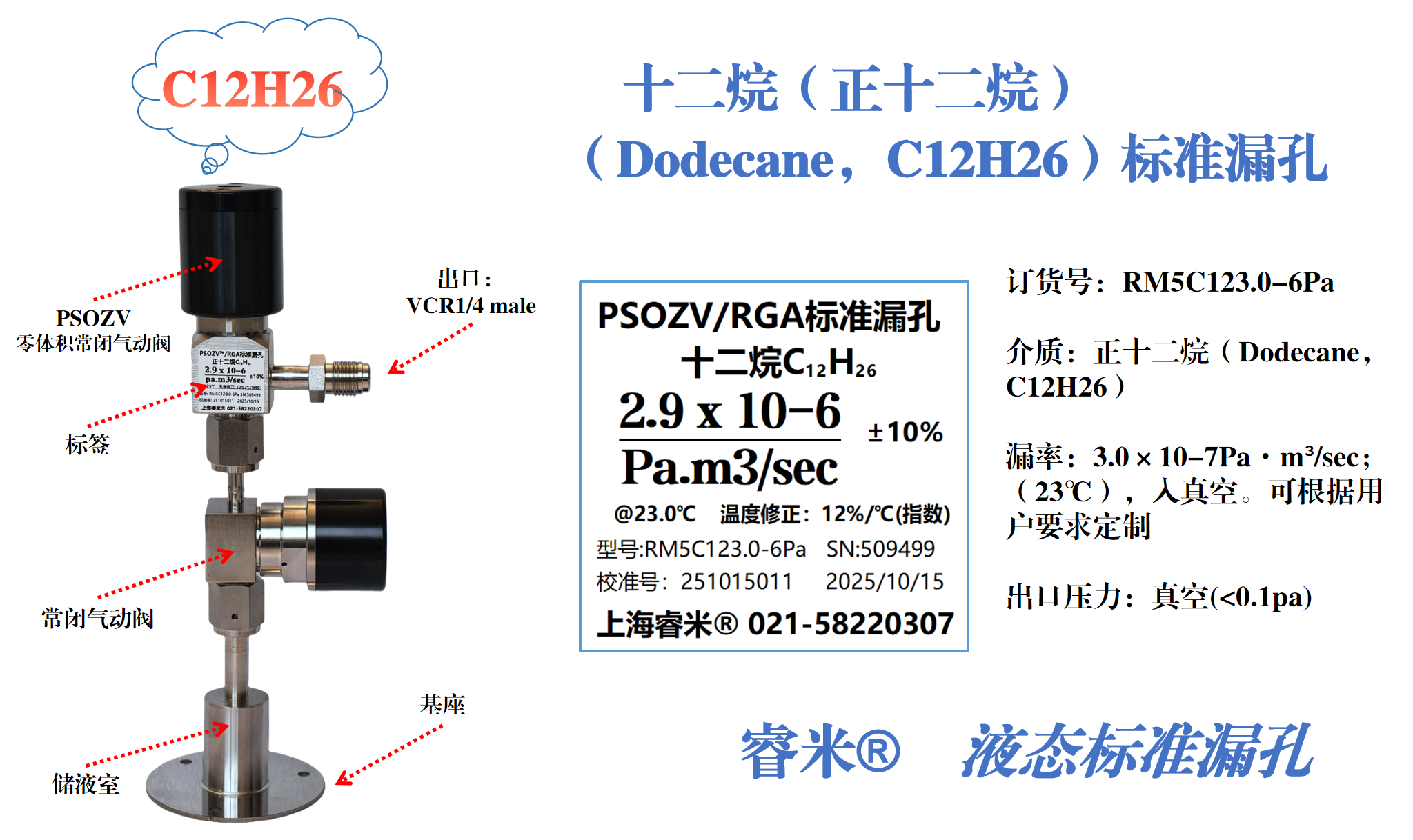
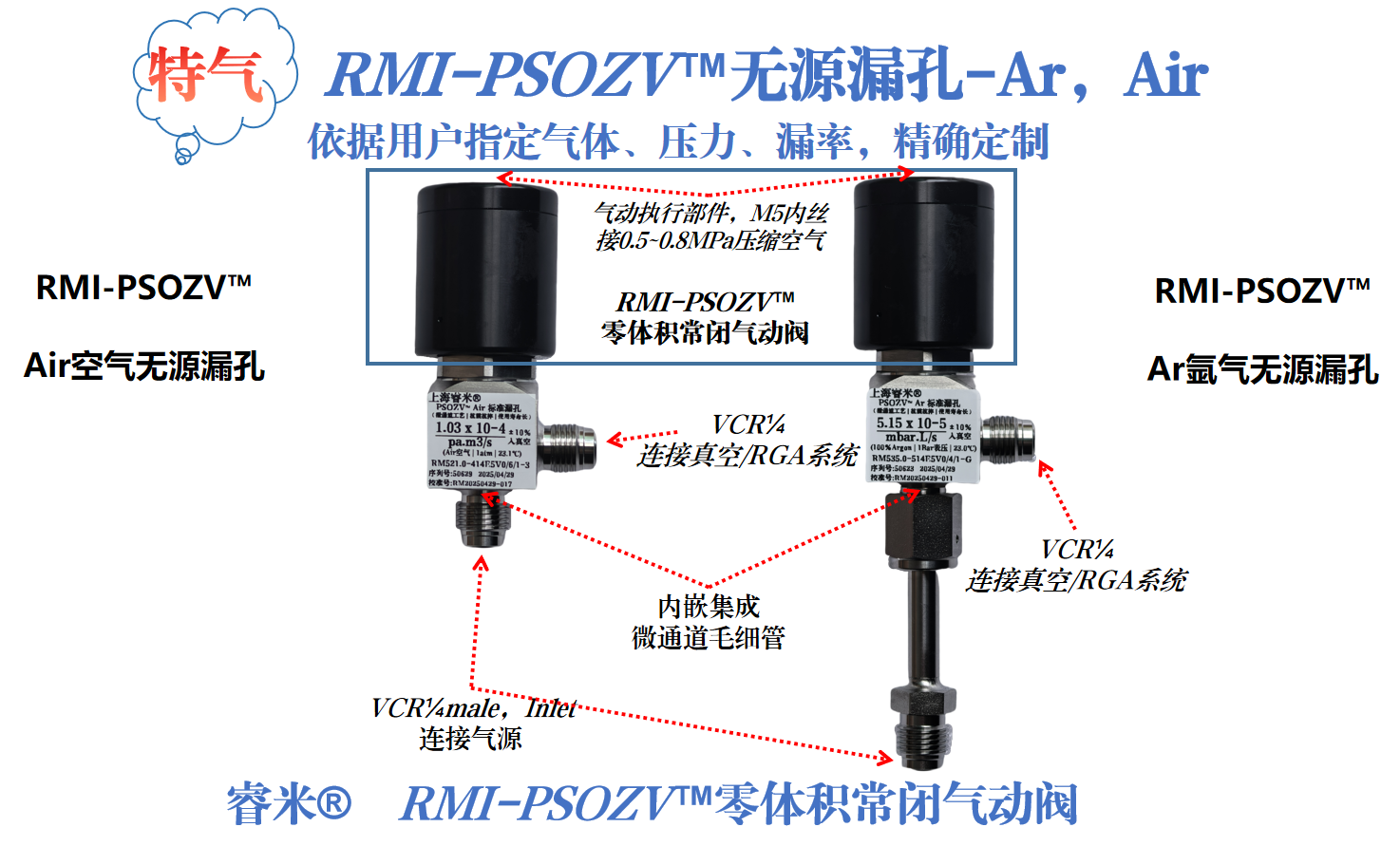
The zero-volume valve aims to push dead volume an order of magnitude below the physical norm. Taking RMI-PSOZV™/MDZV™ as an example, the dead space is Φ0.5 mm × 0.5 mm:
That is 2 ~ 3 orders of magnitude below the 10 ~ 100 μL of conventional valves, and all three calculations of §6.2 shrink in proportion[3]. The two form factors divide the work:
RGA calibration and semiconductor process monitoring make heavy use of gas-mixture calibrated leaks (e.g. 1% each of H₂/He/N₂/Kr/Xe balance Ar, or 1 ppm Kr/Xe balance N₂). There is a widely misunderstood physical point here: in molecular flow, components transport independently, and the partial-rate ratio does not equal the mole-fraction ratio. From Eq. (3-3), the partial rate of component $i$:
An example: 1% He + 99% Ar. In molecular flow the He share of the total rate is
Helium at 1% concentration contributes 3.1% of the rate — the light component is "amplified." Three engineering corollaries:
Semiconductor outgassing analysis, EUV carbon-contamination monitoring and aerospace mass-based acceptance all need liquid-medium standard sources (water, n-dodecane C₁₂H₂₆, DMC, PFTBA, etc.). Their physics differs fundamentally from gas leaks: the liquid evaporates first; the vapor is then transported through the channel — the rate is dominated by vapor pressure:
Vapor pressure depends on temperature exponentially (Clausius–Clapeyron), so liquid leaks carry tempcos of several percent per degree — for n-dodecane, ~12 %/°C (exponential)[8]. Three usage rules follow:
With the physics and hardware of leaks complete, the next chapter enters metrology: how to grade a leak's "accuracy" in the language of uncertainty, and how China's leak-rate values travel from the national primary standard into your hand.
Before uncertainty proper, three concepts that are constantly conflated must be separated — they describe three different qualities of a leak, and no axis can substitute for another:
| Concept | The question it answers | Determined by | Typical expression |
|---|---|---|---|
| Machining precision | Is it made right? (conformance) | Process and simulation capability: is the rate a "designed parameter" or an "emergent result" | Manufacturing tolerance, e.g. ±10% |
| Uncertainty | Is it measured right? (knowledge of the value) | The measurement system: upper-level standard, method, the artifact's behavior during calibration | U = 8% (k = 2) |
| Stability | Does it drift slowly? (time axis) | The leak itself: decay rate, tempco, damage resistance (Ch. 5) | 0.1% ~ 1% per year |
The axes are orthogonal but mutually supporting: however high the machining precision, without low-uncertainty calibration it cannot be proven to a third party; however precise the calibration, poor stability voids the value within months. The most frequent customer-side confusion is taking the manufacturing tolerance for the uncertainty — a leak made to 5×10⁻⁶ mbar·L/s ±10% and then calibrated carries a certificate reading "measured 5.12×10⁻⁶, U = 8% (k = 2)": the ±10% describes manufacturing capability (the scatter of hits around the bull's-eye), the 8% describes how precisely the hit's position is known. The two numbers mean entirely different things and must never be interchanged in contracts or acceptance documents.
"This leak is 1.0×10⁻⁶ Pa·m³/s" — metrologically, that sentence is incomplete. It lacks uncertainty: by how much the value might deviate, with what confidence. The correct expression is "Q = 1.0×10⁻⁶ Pa·m³/s, U = 10% (k = 2)," meaning: with ~95% confidence, the true value lies within [0.90, 1.10]×10⁻⁶. The difference between the two sentences is the difference between a "number" and a "quantity value." Uncertainty is not a cover for error but a score for measurement quality — the smaller it is, the stronger the measurement system behind the leak.
The internationally accepted method is specified by the GUM (Guide to the Expression of Uncertainty in Measurement, adopted in China as JJF 1059.1—2012[11]), in three steps:
cᵢ — sensitivity coefficient (the factor by which the output changes per unit change of the input). The sensitivity coefficient of the temperature-correction term is the temperature coefficient itself — this is why 0.1 %/°C and 4 %/°C are worlds apart in a budget table.
Take the calibration of a 10⁻⁶-class He calibrated leak by the comparison method; a typical budget is shown in Table 7-1 (values are illustrative; actual evaluation rests with the laboratory):
| Component | Type | Source and evaluation | uᵢ / % |
|---|---|---|---|
| Upper-level calibrated-leak value | B | Upper certificate U = 8% (k=2) → u = 4.0 | 4.0 |
| Comparison repeatability | A | n = 10 comparisons, s/√n | 1.5 |
| Intermediate stability | B | Estimated drift between calibrations | 2.9 |
| Readout / instrument linearity | B | MS linear range | 1.0 |
| Temperature effect | B | Control ±2.5 °C × tempco 0.1 %/°C, rectangular ÷√3 (a 4 %/°C permeation leak would reach 5.8) | 0.15 |
| Pressure measurement | B | Pressure-gauge indication error | 0.3 |

How to read a budget matters more than how to compute one: find the dominant components first, then decide what to compress. In this example, "upper-level standard value" and "intermediate stability" contribute nearly 90% of the variance — meaning: refining the detector readout is useless; the only two upgrade paths are a better upper-level standard (move up the traceability chain) and a more stable leak (compress the "intermediate stability" term by design). Swap in a permeation tempco of 4 %/°C and the temperature term alone (u = 4×2.5/√3 ≈ 5.8%) lifts u_c to nearly 8% — tempco is squared in uncertainty combination: the engineering echo of §3.5.
The industry's most confused point: specifications for "leaks" and for "leak detectors" are two separate systems. One table sorts them out:
| Code | Title and object | Scope | Key points |
|---|---|---|---|
| JJF 1833—2020 | Calibration Specification for Vacuum Helium Leaks (object: leaks) | (1×10⁻¹⁰ ~ 1×10⁻⁴) Pa·m³/s | Channel/permeation classification; facility U ≤ 10% (flow-meter / fixed-quantity gas), ≤ 20% (comparison); annual stability ≤ 3%[1] |
| JJF 1627—2017 | Calibration Specification for Calibrated Leaks (Soap-Film Flowmeter Method) (object: leaks) | 1 mL/min ~ 10 L/min; inlet 1 kPa ~ 1.5 MPa, outlet to atmosphere | A primary method for positive-pressure / air-tightness leaks[6] |
| JJG (Mil.) 165—2024 | Verification Regulation for Vacuum Calibrated Leaks (defense system) | Verification of vacuum calibrated leaks | Effective 2025-01-01; RealMeter (Shanghai) is a participating drafter[2] |
| JJF 1986—2022 | Calibration Specification for Differential-Pressure Air Leak Testers (object: testers) | Test pressure ≤ 700 kPa; leak rate (0~100) mL/min | Leak-rate error ±10%; measurement standards include digital pressure gauges and calibrated leaks[9] |
| JJF 1964—2022 | Calibration Specification for Halogen Leak Detectors (object: detectors) | Detectable rates (10⁻⁶ ~ 10⁻⁵) Pa·m³/s | Basis for calibrating refrigerant leak detectors[10] |
The strategic meaning of this map: the detector specifications (1986, 1964) both designate calibrated leaks as the measurement standard — the leak is the intersection of the two systems; if leaks are wrong, the calibration of both detector classes collapses. Meanwhile the leak specifications (1833, 1627, Mil. 165) write "channel/permeation," "annual stability" and "uncertainty" into mandatory language — precisely the projection of this book's Chapters 3~5 physics onto the regulatory level.
To establish a vacuum-helium-leak calibration facility, a metrology institute needs a reference calibrated-leak set covering all orders of magnitude, each piece individually traceable. A typical JJF 1833—2020-compliant configuration (full measured list in §15.3): six leaks covering (3×10⁻¹⁰ ~ 3×10⁻⁵) Pa·m³/s, one per decade; annual stability 0.1% ~ 1.0% (specification requires ≤ 3%); tempco 0.1 %/°C; each piece traceable to national-level institutes such as NIM; recalibration cycle 12 months[3]. Air-tightness and refrigerant media have their corresponding standard-establishing sets (JJF 1627 / JJF 1964 systems).
The enterprise-side logic follows: working leaks follow reference leaks; reference leaks follow the national primary standard. Recommended asset-management actions:
Leak manufacturing and metrological accreditation are two different things. As a manufacturer, RealMeter issues a factory test certificate for every leak shipped; RealMeter calibrated leaks, measured by national metrology institutions, have been procured by multiple metrology institutes/stations as reference calibrated leaks (master standards) for establishing their standards, and RealMeter joined the drafting of JJG (Mil.) 165—2024 as a participating unit[2]. Where customers need CNAS / ISO 17025 calibration certificates, these are issued by metrology institutes (sent out by RealMeter or by the customer). All statements about "certificates" and "traceability" in this book follow this convention.
For any calibrated-leak certificate, check the following in order — 30 seconds tells you whether it is usable:
| Element | What to check | Common defects |
|---|---|---|
| ① Medium & basis | Gas species, concentration; mixtures must state the P/T basis (§6.4) | "Air" without concentration; missing mixture basis |
| ② Inlet pressure | Value + absolute/gauge + unit (§2.4) | "5 bar" without stating absolute or gauge |
| ③ Outlet condition | Vacuum / atmosphere / specified back-pressure (§2.5) | Missing, or mismatched with the usage scenario |
| ④ Temperature & correction | Calibration temperature, tempco, standard state (0 °C convention for sccm) | No tempco; no basis for use away from 23 °C |
| ⑤ Uncertainty & traceability | U value with k, traceability institute, recalibration date | Only the word "pass," no uncertainty |
Reading a real extreme-class certificate against these five elements (a 10⁻¹² Pa·m³/s-class He leak, National Primary Vacuum Metrology Station of the defense industry, July 2026): rate value, Ur = 22% (k = 2), outlet into vacuum, helium medium, upper-level standard with validity date — every element present. The full example is Table 15-1 in §15.1.
Part II is complete: process (Ch. 4), lifetime (Ch. 5), system (Ch. 6), metrology (Ch. 7) — four pieces forming a complete knowledge system for judging any leak. Part III takes this system to the field: leak-test methodology, quantitative RGA, system-level air-tightness accuracy, the helium-reduction paradigm and selection methodology.
Choosing a leak-test method is essentially finding the intersection between "minimum detectable leak rate" and "cost / takt per part":

Three principles for reading the map: first, sensitivity needs margin — the method's detectable floor should sit 1~2 orders of magnitude below the reject threshold (for a 10⁻⁵ threshold, the method should reach 10⁻⁶~10⁻⁷); second, cost jumps in steps — crossing from pressure decay to helium testing lifts equipment and per-part cost by a tier, so "can pressure decay solve this?" is always the first question; third, no method does everything — high-end lines normally combine: pressure decay to screen gross leaks + helium for fine leaks.
A helium leak detector uses a small magnetic-sector mass spectrometer to exclusively "count" ions of mass number 4. The reasons for choosing helium as tracer are textbook material themselves: extremely low natural abundance (only 5.2 ppm in air — clean background), small and penetrating molecules, inert and safe. The three basic modes impose very different demands on leaks:
| Mode | Principle | Sensitivity & traits | Requirements on calibrated leaks |
|---|---|---|---|
| Vacuum method (spray / hood) | Part evacuated and connected to detector; helium sprayed or hooded outside | Most sensitive (10⁻¹¹ class); locates leak points | Reservoir-type vacuum leaks (sensitivity calibration); positive-pressure leaks for sniffer calibration |
| Sniffer method (pressurized part) | Part charged with He (or He mixture); sniffer probe scans outside | 10⁻⁵ ~ 10⁻⁷ class; line workhorse; locates leaks | Passive simulation leaks at same pressure and medium as the part (OK/NG pieces) |
| Bombing method (hermetic devices) | Device pressurized in a high-pressure He tank, then measured for released He in a vacuum chamber | Dedicated to hermetic packages (10⁻⁹ ~ 10⁻¹¹); gross + fine steps | Vacuum calibrated leaks; equivalent standard rate per MIL-STD-type methods |
The sniffer method is the most used — and most misused — mode on production lines: readings depend strongly on probe-to-leak distance, scan speed and ambient He background — it is a "relative comparator," not an "absolute meter." That is exactly why a sniffer line's judgment system must be built with calibrated-leak simulation pieces under identical conditions (the Four-Piece Kit of Ch. 10 and the Three-Reference Verification of Ch. 11 both grow from here).
Air-tightness testing needs no tracer gas: the test volume is charged with air / N₂ to test pressure, stabilized, and the pressure change is monitored. From the definition of leak rate (Eq. 2-1) and the gas law, the pressure drop caused by leakage is:
V — test volume including plumbing (m³); Δt — test time (s); ΔP — pressure drop (Pa). Example: V = 2 L, 10 Pa drop in 10 s → Q = 2×10⁻³ Pa·m³/s = 2×10⁻² mbar·L/s ≈ 1.2 sccm.
Eq. (8-1) is the "Newton's second law" of the air-tightness industry, and it reveals the method's three inherent properties:
The differential-pressure configuration (a differential sensor between the part under test and a reference volume) suppresses temperature and charge-pressure fluctuations by "dual-channel common-mode rejection" and is the mainstream machine type; the direct-decay configuration is simpler but more sensitive to supply and environment. JJF 1986—2022 regulates the calibration of differential-pressure air leak testers (test pressure ≤ 700 kPa, leak rate 0~100 mL/min), one of whose measurement standards is the calibrated leak[9].
Hydrogen testing: uses 5% H₂ + 95% N₂ (non-flammable mixture) as tracer with a semiconductor-sensor sniffer; sensitivity 10⁻⁵ ~ 10⁻⁷ class, far lower cost than helium, no helium-resource dependency — an important alternative on the helium-reduction path; its leak requirements mirror He sniffer testing (H₂/N₂ simulation leaks at same pressure and medium). Halogen / refrigerant testing: uses the refrigerant itself (R134a, R1234yf, etc.) as tracer — the refrigeration industry's regulatory-compliance tool (JJF 1964—2022, detectable 10⁻⁶ ~ 10⁻⁵ Pa·m³/s[10]); since the medium is the product's working fluid, leaks must be calibrated with the real refrigerant and certified on the g/y basis (Eq. 2-2). Water-bubble and ultrasonic: coarse screening above the 10⁻² ~ 10⁻³ class — intuitive and cheap, commonly used as "gross-leak interception" before helium testing.
Two scenarios do not test products directly but are the high-end battlefield of calibrated leaks: first, residual gas analyzer (RGA) quantification — semiconductor and UHV systems use RGAs to monitor process atmospheres and outgassing composition; quantitative calibration needs standard sources of known partial pressure / partial rate: single gases, mixtures (component partial rates, §6.4), isotopes (³He, D₂, ¹⁸O₂, etc.), even liquid-medium vapors (§6.5). Such scenarios are extremely sensitive to valve dead volume and background (the zero-volume valve is a hard threshold, Rule 6-1). Second, mass-flow-controller (MFC) calibration: calibrated leak rates of sccm ~ L/min class serve as flow references, positive-pressure outlet; the soap-film flowmeter method of JJF 1627—2017 is one traceability path[6]. A positioning note is worthwhile here: calibrated leaks and MFCs are complementary, not competing — an MFC is an active control element (regulating flow in real time), while a calibrated leak is a passive reference (a known, stable, traceable flow truth). Use the former to run the process and the latter to calibrate the former — the same division of labor as a variable-frequency drive and a standard resistor.
| Requirement profile | First-choice method | Calibrated-leak form |
|---|---|---|
| Threshold ≥ 10⁻³ mbar·L/s; fast takt, low cost | Differential / decay air-tightness | Passive air-tightness leaks (Air / N₂, same pressure and volume simulation) |
| Threshold 10⁻⁵ ~ 10⁻⁷; leak location needed | He / H₂ sniffer | Passive simulation leak sets (OK / NG / Q₀) |
| Threshold ≤ 10⁻⁷, or hermetic devices | He vacuum / bombing | Reservoir-type vacuum leaks (incl. built-in calibration leaks) |
| Refrigeration regulatory compliance | Halogen / refrigerant testing | Refrigerant calibrated leaks (g/y basis) |
| RGA quantification / semiconductor process monitoring | —— (instrument calibration) | Single-gas / mixture / isotope / liquid leaks + zero-volume valves |
| MFC and flow calibration | —— (flow reference) | sccm-class positive-pressure calibrated leaks |
The next chapter enters the instrument-level main battlefield, and the chapter of heaviest strategic significance: quantitative RGA calibration for semiconductors — from qualitative to quantitative, equipping China's high-end manufacturing with "eyes that can measure."
The core processes of advanced nodes — PVD, CVD, ALD, plasma etch, ion implantation, EUV lithography — all run in vacuum. Each node generation tightens the requirement on vacuum-background purity by roughly an order of magnitude:
| Process step | Typical vacuum / mbar | Key monitored gases | Contamination tolerance |
|---|---|---|---|
| PVD metal deposition | 10⁻⁸ ~ 10⁻⁹ | Ar, H₂O, O₂, N₂ | H₂O < 1 ppb |
| CVD dielectric deposition | 10⁻⁶ ~ 10⁻⁸ | SiH₄, NH₃, by-products | Cross-contamination < 10 ppb |
| ALD high-k dielectric | 10⁻⁷ ~ 10⁻⁹ | H₂O, TMA, carrier gas | H₂O < 0.1 ppb |
| Plasma etch | 10⁻³ ~ 10⁻⁵ | CF₄, SF₆, BCl₃, by-products | Endpoint detection ±1% |
| Plasma etch | 10⁻³ ~ 10⁻⁵ | CF₄, SF₆, BCl₃, by-products | Endpoint detection ±1% |
| EUV lithography | 10⁻⁸ ~ 10⁻¹⁰ | H₂, Xe, Sn vapor | Mirror contamination < 1 ppt |
The meaning of this table: at the deepest level, the competition of advanced manufacturing is a competition of trace-contamination metrology capability. ppm-level contamination can scrap an entire wafer lot, and the only instrument that can simultaneously resolve multiple gas species and their partial pressures in vacuum is the RGA (quadrupole residual gas analyzer). The RGA is the "eye" of high-end equipment; and all the argumentation of this book's first eight chapters condenses into one sentence: eyes need a yardstick, and the yardstick must be traceable. Vacuum acceptance of semiconductor tools, contamination monitoring of process chambers, incoming inspection of high-purity materials, root-cause tracing in failure analysis — these links have long depended on imported calibration means. Making the RGA calibration system self-reliant fills in the lowest-level piece of the "metrology foundation" for high-end manufacturing. That is why this chapter stands alone — and why it is the largest growth market of the calibrated-leak industry over the next decade.
The quantitative basis of an RGA is the linear relation between ion current and partial pressure:
I_g — ion current of gas g's characteristic peak (A); P_g — partial pressure (mbar); S_g — sensitivity factor (A/mbar), jointly determined by electron energy, ion-source geometry, quadrupole transmission function and detector gain, and drifting with filament aging and contamination.
Eq. (9-1) is structurally identical to Eq. (8-1) of air-tightness testing: instruments output "signals"; between signal and "quantity value" stands a coefficient that must be calibrated periodically. The three stages of RGA application are essentially the history of calibrating that coefficient:
| Stage | Capability | Limitation / breakthrough |
|---|---|---|
| ① Qualitative monitoring (1970s~90s) | Watch the water peak (m/z 18) and air peaks (28/32) to judge vacuum health | "Is something wrong" — no numbers |
| ② Semi-quantitative (1990s~2010s) | Built-in gas library + sensitivity factors; rough quantification of common gases | Error ±30% ~ ±100%; blind to organic vapors and trace impurities |
| ③ Absolute quantification (2010s~) | In-situ calibration with calibrated leaks, permanent gases → organic vapors → ppm traces | The calibration system decides accuracy: liquid and mixture leaks fill the blind zones |
First, the sensitivity-factor method. Connect a pure-gas calibrated leak of known rate to the system, record the ion current at steady flow, and solve directly for $S_g = I_g / P_g$. Two engineering points: the zero-volume valve lets calibration run in-situ on production tools without shocking the vacuum (Ch. 6); annual decay below the 0.2% class makes calibration results portable and reusable.
Second, the calibrated-leak comparison method. For target sources that cannot be measured directly, compare signals against a known leak at the same pumping speed:
For extremely low rates (< 10⁻¹¹ Pa·m³/s), use the static accumulation method: isolate the pumps and measure the rate of pressure rise in volume $V$:
Note that Eq. (9-3) is the same formula as Eq. (8-1) of air-tightness testing — vacuum accumulation and positive-pressure decay are physical mirror images: the recurring theme of this book that "leak rate has only one physics."
Third, fragmentation-pattern analysis. In mixtures, every mass peak is a linear superposition of multiple components:
α_Mg — fragmentation factor of gas g at mass number M. The main peaks of CO / N₂ / C₂H₄ overlap completely at m/z 28; separation must rely on fragment differences (CO at m/z 12, C₂H₄ at m/z 27) — and calibrating the fragmentation-factor database requires mixture calibrated leaks of precisely known composition as input.
Fourth, the liquid-medium quantification breakthrough. Water vapor, photoresist solvents (DMC), pump-oil tracers (PFTBA) and n-alkanes (organic-contamination fingerprints) have long been the RGA's "organic-vapor blind zone": vapor pressure varies exponentially with temperature, gas-phase standards are lacking, and the high-m/z region has no response reference. Microchannel controlled-release liquid leaks (liquid–vapor equilibrium + microchannel flow-resistance release), combined with known temperature coefficients (9~12 %/°C, §6.5), turn the blind zone into a quantifiable one (±10% class) — PFTBA fragments spanning m/z 69~671 are the recognized gold standard for high-mass calibration[13].
Advanced processes need the ability to verify "ppb-level impurities in the process background." The two-stage dilution architecture of ppm-class mixture leaks provides the answer: Kr/Xe at 1 ppm in the source gas (first-stage dilution), with the ratio of total leak rate to system pumping speed further suppressing the partial pressure (second stage):
Q_total — total leak rate; C_Kr — Kr mole fraction in the source; S_eff — effective pumping speed. What the RGA "sees" of Kr is set by the ratio of Kr partial rate to pumping speed.
| Total rate / mbar·L/s | Kr source conc. | Kr partial rate / mbar·L/s | Pumping speed / L/s | Kr partial pressure / mbar | Relative level |
|---|---|---|---|---|---|
| 10⁻³ | 1 ppm | 10⁻⁹ | 100 | 10⁻¹¹ | ~100 ppm |
| 10⁻³ | 1 ppm | 10⁻⁹ | 1000 | 10⁻¹² | ~10 ppm |
| 10⁻⁶ | 1 ppm | 10⁻¹² | 100 | 10⁻¹⁴ | ~100 ppb |
| 10⁻⁶ | 1 ppm | 10⁻¹² | 1000 | 10⁻¹⁵ | ~10 ppb |
| 10⁻⁹ | 1 ppm | 10⁻¹⁵ | 1000 | 10⁻¹⁸ | ~10 ppt |
Note: "relative level" is the Kr partial pressure as a fraction of a typical 10⁻⁷ mbar system background (e.g. 10⁻¹¹/10⁻⁷ = 100 ppm).
One table spanning six orders of magnitude — the "input end" of trace verification thus becomes traceable. The other half of the problem is mass discrimination: quadrupole transmission efficiency varies with mass number, and the response at m/z 132 can differ by orders of magnitude from m/z 28. The natural multi-isotope abundances of Kr (78~86 amu) and Xe (124~136 amu) are "mass rulers written into physical constants": comparing measured isotope ratios against theoretical values yields the transmission correction factor at each mass, building a cross-mass sensitivity response curve (Fig. 9-1).

| Stage | Calibration task | Leak configuration |
|---|---|---|
| Tool manufacturing & acceptance | Ultimate-vacuum "gas fingerprint," detector sensitivity, pump-speed verification, material outgassing rate | He / N₂ / Ar / H₂O single-gas leaks + mixture leaks |
| PVD | Ar working-gas purity, <1 ppb water-vapor quantification | Ar leak (m/z 40 sensitivity) + H₂O liquid leak |
| CVD / ALD | Precursor residue, post-clean baseline recovery, H₂O precursor residue | N₂ / Ar references + ppm mixtures + H₂O leak |
| Plasma etch | Endpoint detection ±1% (e.g. m/z 69 CF₃⁺ response) | Ar / CF₄-type mixture simulation leaks |
| Lithography / EUV | Photoresist volatiles quantification, Xe residue, post-purge trace verification | DMC liquid leak + Xe leak + 1 ppm Kr/Xe mixture |
| Chamber-clean verification | Wet-to-dry time optimization, water-peak quantitative tracking | Ar / N₂ fingerprints + H₂O leak |
| Material incoming inspection | ppb-level impurities in high-purity gases, moisture in specialty gases | ppm-class mixture leaks + H₂O leak |
| Packaging / failure analysis | In-package atmosphere, moisture, contaminant spectral library | He / N₂ / Ar + H₂O / organic-vapor leaks |
Calibration coverage assessed by stage: tool vacuum acceptance > 95%, PVD > 95%, lithography / clean verification > 90%, packaging & test > 95%, material incoming > 90%; CVD / ALD / etch / implantation, which involve reactive specialty gases, about 65% ~ 70% — reasons in the next section[13].
A responsible white paper must state its boundaries. Reactive / corrosive / highly toxic specialty gases — SiH₄, AsH₃, PH₃, WF₆, TMA, Cl₂, HBr, NF₃, F₂ — cannot currently be made into stable calibrated leaks — the reason lies in gas physics itself (decomposition inside microchannels, lethal safety risks, channel corrosion, strong adsorption), not in process capability; even in the markets with the most advanced calibrated-leak technology, such leaks are equally scarce or nonexistent. "Surrogate-gas calibration" serves trend judgment only within a narrow window (single mass number, no overlapping peaks, no memory effect) and introduces 20% ~ 100% systematic error — tactically usable, strategically undependable.
The industry's mature solution is a cross-sensor complementary architecture: direct measurement of specialty gases goes to FTIR, OES and electrochemical sensors; the RGA returns to its "environmental watchdog" role — process-fingerprint baselines, cross-contamination monitoring, clean verification, and indirect inference via correlated parameters (e.g. for WF₆, watch not m/z 298 but the by-product SiF₄ at m/z 85). In this architecture, the calibrated leak's task is to keep the RGA's long-term response stable — precisely the value zone of low-decay, zero-dead-volume leaks. Best practices for consistency: sensitivity factors recalibrated every 3~6 months, in-situ first, mixtures for cross-checking the high-mass region, liquid media calibrated specifically every 6 months[13].
Putting this chapter back in the big picture: self-reliance in semiconductor equipment ultimately comes down to "every tool's vacuum performance being credibly verified at shipment, and every wafer's process environment being credibly monitored." The credibility of verification and monitoring, in turn, ultimately comes down to whether the calibration system is self-reliant and traceable. For a long time, high-end calibration leaks and RGA quantification methods were bundled inside imported supply systems; once the microchannel process made "all media (single gases / mixtures / isotopes / liquids), all leak rates (10⁻³ ~ 10⁻¹⁰ mbar·L/s), in-situ zero-shock calibration" a routine domestic supply, the last mile of upgrading RGA from a "reference tool" to a "metrological instrument" — the calibration link — was opened. As fabs expand and nodes advance (below 2 nm pushing tolerances toward ppt), this market grows not linearly but multiplicatively with "verification stations × calibration frequency." The directions are equally clear: lower concentrations (ppb → ppt mixtures), wider mass range (> 500 amu precursors), materials-science breakthroughs for reactive-gas calibration, and automated periodic calibration integrated with RGA software.
The next chapter returns to the main battlefield of production-line application: system-level accuracy of air-tightness testing.
From Eq. (8-1), judging leakage = judging pressure drop. The problem: pressure is not changed by leakage alone. For a sealed volume, the gas law gives the direct effect of temperature on pressure:
Insert typical line conditions: test pressure 20 kPa gauge (~121 kPa absolute), ambient 27 °C (300 K), a 1 °C drift of part or environment within the test cycle:
A 1 °C temperature drift ≈ a 400 Pa pressure drift. And what is a typical decision ΔP in air-tightness testing? Tens of Pa. In other words, temperature noise is an order of magnitude larger than the leak signal — any practice of "set an allowable ΔP and judge OK/NG" is physically equivalent to measuring microns with a thermally expanding ruler. The differential-pressure architecture (common-mode comparison between reference and test part) cancels slowly varying common-mode temperature fields, but not two residuals: the temperature difference between test and reference parts (uneven incoming temperatures, hot parts fresh off the line), and the asymmetry of adiabatic effects (gas heats on charge compression, then loses heat to the walls, pressure settling exponentially with a time constant of seconds — Fig. 10-1).

| Error source | Mechanism | Typical magnitude | Countermeasure |
|---|---|---|---|
| Ambient / part temperature difference | Eq. (10-1), ΔP = P·ΔT/T | 1 °C → ~400 Pa | Climate zone, incoming-temperature management, differential common mode |
| Adiabatic compression | Charge heating → heat loss to walls | Hundreds of Pa, exponential over seconds | Sufficient stabilization time (Fig. 10-1 decision window) |
| Fixture / part elastic deformation | Volume changes with pressure, V shifts | Structure-dependent; can exceed leak signal | Rigid fixtures, stops, identical reference part |
| Sensor zero drift & resolution | The differential sensor itself | 0.1 ~ several Pa | Periodic calibration (JJF 1986—2022[9]) |
| Volume calibration error | V in Q = ΔP·V/Δt is inaccurate | Several percent (relative) | Calibrate V with a calibrated leak, never estimate from drawings |
Conclusion: ΔP-based judgment is essentially "substituting physical assumptions for verification" — assuming uniform temperature, assuming known volume, assuming completed thermal equilibrium. All three assumptions hold in the laboratory and are doubtful on the line. The way out is not a pricier sensor but making "judgment capability" a daily-verifiable system: the Golden-Part Four-Piece Kit.
The same cognitive traps exist on the helium side, more insidiously. First, what a leak detector displays is not a leak rate but an ion current — filament aging can make the same leak rate produce signals differing severalfold; the reading only acquires physical meaning through a calibration factor (CF), and an uncalibrated reading is a number without dimensions. Second, single-point calibration cannot cover the full range — ion-source contamination drifts the capture efficiency differently at each magnitude, and system conductance changes with flow regime (viscous for large leaks, molecular for small ones, Ch. 3), so extrapolated "linearity" across decades is a dangerous assumption. Third, a 100% He leak cannot be rescaled to a low-concentration condition — partial pressure is not total pressure, and a mixture transports through micro-orifices differently from pure helium (§6.4); low-concentration testing must be verified with same-concentration simulation leaks under real conditions. All three point to one rule: calibrate near the threshold, verify under real working conditions — the Three-Reference Verification of the next chapter is exactly this rule, systematized.
The datasheet's "accuracy 0.1% FS" describes a sensor; what the line needs is judgment. The gap between the two is opened by four links: tooling, environment, part condition, operation. System-level thinking splits leak judgment into three layers, each verified with a different standard piece:
One common counter-example of the three-layer architecture must be named: a line that relies solely on the tester's "self-check" is essentially a black box. The self-check calibrates the instrument against a built-in leak, yet the built-in leak's own drift is verified by no one — using an unverified ruler to verify the ruler is a circular argument; and a built-in leak usually provides a single rate point, so single-point fitting extrapolated to other magnitudes is unreliable (cognitive trap no. 2 at the end of §10.1). The credible practice is a dual evidence chain: a reservoir-type leak verifies the instrument itself (machine level — "is the gauge right"), while passive simulation leaks verify the system under real pressure, real medium and real takt (fixture / system level — "is the job right"). If the former fails, the instrument is flying blind; if the latter is missing, the whole line is judging blind. Neither is dispensable.
The Four-Piece Kit is the minimal complete configuration for system-level verification[7]:
| Piece | Physical composition | Verification goal & frequency |
|---|---|---|
| Q₀ check piece | Calibrated leak (rate = reject threshold or sensitivity class) | Per shift / daily check: instrument reading-drift monitor; machine level |
| OK dummy | Golden part + built-in / side-connected calibrated leak, total rate = (1/3 ~ 1/2) × threshold | Fixture level: must judge OK stably (false-reject guard) |
| NG dummy | Golden part + calibrated leak, total rate = (2 ~ 3) × threshold | Fixture level: must judge NG stably (missed-reject guard) |
| Golden part | A reference part confirmed leak-free by helium testing (or equivalent sealed dummy) | Carrier and reference for OK / NG dummies |
The logical loop of the kit: the OK piece guards the false-reject line, the NG piece guards the missed-reject line, Q₀ guards instrument drift, and the golden part provides a trustworthy carrier. Run all four pieces at the start of each day, and the "today's health" of the judgment system is immediately known — turning the physical dilemma of §10.1 from "assumptions" into "daily measurement." Two engineering details: first, the OK/NG dummy leaks should be built into or side-connected inside the golden part, so that leak path, volume and temperature response match the real part (five identical conditions of simulation: same volume, pressure, medium, temperature, takt[7]); second, the stability of the leaks themselves is the premise of the kit's credibility — if a dummy's leak drifts with temperature (permeation +4 %/°C) or decays off, the referee's ruler changes by itself; this is why the kit prefers channel-type low-tempco leaks (Table 3-2).
Terminology note: the Q₀ + OK + NG pieces form the core verification logic; the golden part is their realistic carrier in pressure-decay scenarios (making leak path, volume and temperature response identical to real parts). In tracer-gas (helium) testing, the same verification system is called the Three-Reference Verification — with the same decision criteria: GR&R ≤ 15% + three-tier separation (Ch. 11). OK / NG dummy rates are (1/3~1/2) Q₀ and (2~3) Q₀ throughout this book.
How a calibrated leak is connected to the test system directly decides the credibility of the verification value. Four connection methods form a ladder from low to high fidelity:
| Method | How it is done | Main error | Applicability |
|---|---|---|---|
| ① Direct quick-plug | Leak plugged into the instrument's calibration port | Completely decoupled from the fixture | Instrument-only verification (machine level) |
| ② Line tee-in | Leak connected into the charging line | Path differs from the part | Coarse verification |
| ③ Built into dummy | Leak embedded inside a golden-part dummy | Dummy fabrication needed | Standard practice for OK/NG dummies |
| ④ Bypass method | Leak connected across the test volume via a bypass valve; opened mid-test to inject a known leak | Minimal (real part, real plumbing, real takt) | Highest grade of system verification and volume calibration |
Bypass-method SOP (system-level accuracy verification and equivalent-volume calibration):
Once the system is built, prove it metrologically: take samples near the boundary (OK dummy, NG dummy and borderline parts), run repeated measurements by multiple operators, and perform a GR&R (gage repeatability & reproducibility) analysis; for attribute judgment (OK/NG), run an attribute agreement analysis (Kappa). Common industry thresholds: variable GR&R ≤ 10% acceptable, 10~30% risk-dependent, > 30% unusable; for OK/NG judgment systems, the more direct engineering criterion is GR&R ≤ 15% + three-tier separation (OK, Q₀, NG readings clearly tiered without overlap, §11.3). A GR&R report is also the language most accepted by OEMs and auditors — the Four-Piece Kit is the daily thermometer; GR&R is the periodic health check.
This chapter solved system accuracy for "air testing"; the next chapter solves the cost dilemma of "helium testing": in the era of helium at 300+ RMB/m³, how to cut helium usage by one to two orders of magnitude without losing judgment capability.
In March 2026, escalating geopolitical conflict in the Middle East severely damaged facilities at Ras Laffan Industrial City in Qatar — the world's second-largest helium production base — with repairs expected to take 3~5 years; together with the United States, Qatar forms the two pillars of global helium supply (30%~39% of the world total). Chinese landed prices for industrial-grade helium soared from 50~70 RMB/m³ in 2025 to 300~400 RMB/m³ in April 2026, a 5~10-fold increase. China's helium consumption relies on imports for about 90%, of which 54%~66% comes from Qatar — even those willing to pay the premium may not secure a stable quota[12]. "Reducing helium consumption per test" has upgraded from a cost-optimization option to an industrial-survival option.
Under the crisis, the industry shows three mindsets:
| Mindset | State of mind | The problem |
|---|---|---|
| Pure-He fundamentalists | "Pure helium is the only standard; any concentration cut means risk" | The belief is unverified — pure helium itself cannot guarantee reliability (§11.3) |
| Reluctant reducers | Already down to 80%, 60% He, but "honest in body, not in faith," planning to return to pure He once prices fall | The unease comes from "no verification," not from "lower concentration" — they never ran three-reference verification at 80% He, nor did they at 100% He |
| Three-Reference verifiers | "Verification passed = system reliable, regardless of concentration" | The correct cognition — needs promotion |
The key cognitive shift: from "concentration determines reliability" to "verification determines reliability." "80% He is less reliable than 100% He" is an untested assumption — the correct comparison is "80% He + three-reference verification = reliability confirmed" versus "100% He + no verification = reliability unknown." Concentration anxiety is unsolvable (helium prices are beyond your control); verification anxiety is solvable (three references, a few minutes per shift).
All air-tightness and leak testing does exactly one thing: compare the size of the equivalent leak channel on the workpiece (§1.4). Split this judgment into four layers and the industry's misconceptions become visible at a glance:
| Layer | Content | Variable? | Industry misconception |
|---|---|---|---|
| Physical reality | The workpiece's equivalent orifice d₀ | Immutable | Ignored |
| Purpose | Judge d > d₀ (NG) or d < d₀ (OK) | Immutable | Distorted into "precise measurement" |
| Means | Tracer gas: 100% He / 1% He / Air / N₂ | Replaceable | "Only pure helium works" |
| Reading | The mbar·L/s number on the instrument | Varies with means | The number is mistaken for physical reality |
Whether you charge 100% helium or 1% helium, the physical orifice on the workpiece does not change by a single micron — leak rate Q is a function of gas species, pressure difference, temperature and flow regime (Eq. 3-1 ~ 3-4), not an intrinsic property of the leak channel; switching concentration only changes the mixture's mean molar mass and effective partial pressure. The industry's core misconception is mistaking the fourth layer (the reading) for the first layer (physical reality), and mistaking one option in the third layer (100% He) for the only option.
A long-overlooked fact: air leak testers proved long ago that non-helium gases can reliably compare orifices. A differential-pressure air tester uses compressed air (containing only ~5 ppm helium) as medium, has no mass spectrometer, and still judges Pass/Fail stably on production lines (Ch. 10). From air testing → low-concentration helium testing → pure-helium testing is a continuous spectrum, not a black-and-white boundary — if testing's essence were "absolute accuracy of the instrument reading," air testers could not work at all; they do work, which means the essence is "sufficient discrimination." The ultimate output of line testing is a binary Pass/Fail; the core need is judgment consistency, not absolute accuracy.
Under ideal conditions, this judgment can be written as clean mathematics. The helium-test signal (sniffer or vacuum method) for a leak Q is:
S — instrument signal (rate reading); k — instrument sensitivity coefficient (transmission, ionization, amplification); c — helium concentration in the tracer gas; Q — total leak rate of the workpiece's leak point.
Measure the workpiece and the calibrated leak under the same concentration of tracer gas (same source), and take the signal ratio:
In the ratio $R$, $k$ and $c$ cancel approximately — this is the ideal model of judgment. But note: it is only a zero-order approximation; the deviation sources and engineering countermeasures follow in §11.3.
Early versions of the helium-reduction argument (including this book up to V1.2) stated the cancellation in Eq. (11-2) as "exact." Deep engineering practice has shown this statement over-idealized; it needs correction. Real systems exhibit three classes of deviation:
The methodology must therefore complete three turns: from "mathematical cancellation" to "engineering comparison" — no longer pursuing a proof that the concentration term cancels exactly; three-reference measured verification replaces mathematical cancellation as the basis of judgment. From "single-piece Q₀ calibration" to "Three-Reference Verification" — Q₀ + OK + NG verified together, ensuring the system works reliably in its actual state of the day. From "theoretically determined concentration" to "iterating to the MWC" — not presuming 1% must work; use the stepwise concentration-reduction method to find each scenario's optimal concentration by measurement (§11.4). This correction does not weaken the scheme's reliability — it strengthens its honesty and operability.
Three-Reference Verification (Q₀ + OK + NG) is the gold standard of leak testing — whether at 100% He or 1% He, whether or not helium is reduced:
| Reference | Leak rate | Verification goal | Scale analogy |
|---|---|---|---|
| Q₀ threshold piece | = reject threshold | Anchor the Pass/Fail boundary | 1 kg weight — does the scale read 1 kg? |
| OK piece | (1/3 ~ 1/2) Q₀ | Verify "no false rejects" (good parts not killed) | 0.5 kg weight — surely it won't read 1.2 kg? |
| NG piece | (2 ~ 3) Q₀ | Verify "no missed rejects" (bad parts always caught) | 2 kg weight — surely it won't read 0.8 kg? |
Run all three references at the start of each day / shift — this is the correct way to open a leak-testing line. Only two conditions decide system usability: ① system GR&R ≤ 15% (the common measurement-system-analysis standard); ② three-tier separation (OK, Q₀, NG readings clearly tiered, no overlap). When both hold, the system works — whether on 100% He, 1% He, or air. The discrimination ratio (measured reading ratio) is a natural consequence of the two conditions rather than an independent constraint: with the conventional choices OK = (1/3~1/2)Q₀ and NG = (2~3)Q₀, even at SNR as low as 3 the discrimination ratio typically stays between 2~5; GR&R ≤ 15% keeps within-tier fluctuation far below the inter-tier gap, leaving no "gray zone" between tiers (Fig. 11-1).

This is the dividend of the paradigm shift: the traditional "absolute metrology" paradigm demands SNR ≥ 10 (the rate value must be known precisely); the "size comparison" paradigm needs only SNR ≥ 3 ~ 5, provided GR&R ≤ 15% — from "precise measurement" to "sufficient discrimination," the threshold drops dramatically.
There is also a frequently inverted positioning of Three-Reference Verification: it is not an accessory of helium reduction — it is the best practice even under pure helium. 100% He solves only the single dimension of "signal strength," while test reliability is a system engineering of instrument, environment, operation and standards — instrument sensitivity drift (filament aging, electronics drift — concentration-independent), environmental background spikes after gross leaks (pure He makes gross leaks dump more helium and pollute worse), calibrated-leak self-drift (permeation leaks decay 1%~5%/year — concentration-independent), fixture and operation differences, vacuum-system micro-leaks: none of these five problem classes disappears automatically under pure helium. Thought experiment: two lines both on 100% He — line A, which never verifies, may "fly blind" for months after 30% filament aging, shipping batches of missed rejects unnoticed; line B, verifying daily, would spot an 18% drift of the Q₀ reading on day three and act immediately. The problem has never been concentration; it is whether you verify. Helium reduction is an extension of Three-Reference Verification — since you should verify daily anyway, finding the lowest workable concentration along the way is pure cost saving: what helium reduction cuts is cost, not quality.
The Minimum Working Concentration (MWC) is not computed — it is measured, through three-reference verification. The procedure: first establish baseline readings of the three references at 100% He and record the discrimination ratio (Step 0); then step down through 50% → 20% → 10% → 5% → 2% → 1%, re-running the full three-reference verification at each level — if the three tiers stay clearly separated, keep descending; if tiers overlap or GR&R > 15%, stop, and MWC = the previous level. Every part–equipment combination finds its own optimum this way — the methodological upgrade from "guessing 1%" to "scientifically finding the optimum." Two execution details: first, the iteration must run at the target takt — verify with the same integration time as the line's actual takt (minimum detectable rate depends on integration time; a 3~5 s/part ultra-fast line has different margin than a tens-of-seconds conventional line, though even the fastest lines retain large margin in industrial helium testing); second, record environmental parameters such as temperature and humidity alongside.
Reference starting concentrations by threshold magnitude (iteration starting points, not conclusions):
| Threshold class | Typical applications | Reference starting conc. | Notes |
|---|---|---|---|
| 10⁻⁴ mbar·L/s | Automotive A/C lines, ordinary refrigeration parts, general industrial seals | 1% ~ 3% | Huge margin; no pressure at any takt |
| 10⁻⁵ mbar·L/s | Battery cases, refrigeration compressors, medium-seal industrial parts | 1% ~ 5% | Core application range; the economic "sweet spot" |
| 10⁻⁶ mbar·L/s | High-seal relays, some medical devices, aerospace critical seals | 10% ~ 20% | Higher concentration needed to pass verification; still saves 80%~90% vs pure He |
Low concentration carries a counter-intuitive dividend: the active noise-reduction effect. On pure-He lines, test exhaust (about 60%~70% of total emissions), joint and seal micro-leaks, part-surface desorption and calibration exhaust can push the workshop's local helium background from the natural 5 ppm to hundreds or even thousands of ppm; switching to a 1% mixture cuts the absolute helium emitted per test by ~100×, total workshop He emissions by ~99%, and the background returns to natural levels. The "memory effect" after gross-leak parts (helium adsorbed on mass-spectrometer chamber walls releasing slowly, conventionally requiring minutes to tens of minutes of clean-up waiting) shrinks to seconds under the mixture scheme, since the absolute helium flushed in drops by two orders of magnitude — no shutdown needed. In SNR = signal / noise: the numerator (signal) falls with concentration, but the denominator (ambient He interference) falls even more — at sites with severe ambient helium pollution, the effective SNR may actually rise rather than fall. This is the scheme's core insight: "counter-intuitive" yet "physically rigorous."
A simple flow-regime guide: molecular flow (Kn ≫ 1) — signal-vs-concentration is approximately linear, but three-reference verification is still mandatory; transitional flow (0.01 < Kn < 1) — possibly nonlinear, verification absolutely required; viscous flow (Kn < 0.01) — significantly nonlinear, helium reduction not recommended. All flow-regime effects are absorbed by three-reference comparison — every step of concentration iteration trusts measurement, not theory.
Helium cost ≈ usage × concentration (at fixed recovery rate, Fig. 11-2):

A concrete ledger (battery-pack helium-testing line, 5~6 million parts/year, industry operating-data caliber[12]): the pure-He scheme consumes ~300 cylinders/year (50 L × 20 MPa, ~3,000 RMB/cylinder), ~900,000 RMB/year of helium; at 10% concentration, consumption falls to ~30 cylinders, ~90,000 RMB — annual savings of about 800,000 RMB — while the one-time investment for Three-Reference Verification is only 10,000~30,000 RMB (Q₀ calibrated leak + OK / NG dummy fabrication), and mixing equipment costs far less than recovery systems. The hidden gains are equally substantial: daily three-reference verification eliminates batch misjudgment from systematic drift (false-alarm rates can drop by 50%+); post-gross-leak clearing time falls from minutes to seconds, lifting effective takt by 3%~8%; per-shift three-reference calibration records give quality audits evidence (satisfying IATF 16949 and similar systems); and low consumption is itself a supply-chain risk hedge.
The ledger has a second dimension — the total cost of ownership (TCO) of the standard itself. The hidden expenses of conventional permeation / glass-process leaks are spread over three items: transport losses and accidental scrap from fragility, frequent recalibration trips with line-down waiting, and batch misjudgment caused by drift. Leaks with low decay (0.1% ~ 2.5%/year, §16.3), proven drop/freeze performance (§15.2 measurements), and wide-temperature, no-special-storage operation stretch the recalibration cycle reliably to 12 months (the §15.3 apparatus example) and remove "handle with kid gloves" from daily work. These savings are not denominated in helium, but they reach the income statement just the same. At selection time, replacing "unit price" with "TCO = purchase price + recalibration fees × years + scrap rate × replacement cost + misjudgment risk cost" often reverses the conclusion.
Helium reduction is not a point technology but a three-factor product of "concentration × recovery × judgment method" — and the judgment-method factor (Three-Reference Verification) happens to be the cheapest and purest cognitive lever of the three. The bigger picture: when industrial helium testing cuts helium usage to 10% of before, the same import volume supports more than 10× the testing demand, domestic limited capacity becomes "enough," and the helium crisis is dissolved on the demand side — a "demand-side revolution" that also gives China the chance to become the definer of low-concentration helium-testing standards[12].
An honest white paper must state its boundaries clearly. Applicability by test method:
| Method | Applicability | Core requirement | Notes |
|---|---|---|---|
| Vacuum method | Most thoroughly proven | Chamber sealing, sufficient pumping speed | Dual benefit of He reduction (signal ↓, background ↓↓) |
| Positive-pressure accumulation | Fully feasible | Sealed accumulation chamber, time control | Essentially similar to vacuum method; common in the battery-pack industry |
| Sniffer method | Feasible but higher bar | Intake flow must be constant (MFC / constant-flow pump) | Ambient He background fixed at ~5 ppm: reducing He does not reduce noise, SNR falls strictly; MWC usually higher than vacuum method |
| Pressure decay / differential | Not applicable | —— | Air is the medium; no tracer-concentration concept (its system-level verification is Ch. 10) |
The final chapter of Part III returns to the most everyday question: given a requirement, how to choose the right leak step by step — and the pitfalls we have stepped into over the years.
Selection is essentially fixing the "four working-condition elements + form" of Chapter 2. Converge in the following five steps, each mapping to earlier chapters:
| Step | Question to answer | Chapters & key points |
|---|---|---|
| ① Fix the medium | What gas? Pure / mixture / refrigerant / liquid? Concentration and P/T basis? | §6.4 mixture basis; §6.5 liquid media; refrigerant g/y (Eq. 2-4) |
| ② Fix the rate | What is the reject threshold? Sensitivity verification or OK/NG simulation? | Threshold × (1/3~1/2) for OK pieces, × (2~3) for NG pieces (§10.3) |
| ③ Fix the pressure | Inlet pressure (absolute!), outlet condition (vacuum / atmosphere)? | §2.4 gauge vs absolute; §2.5 positive/vacuum bases (Rule 2-1) |
| ④ Fix the form | Reservoir or passive? Fittings and mounting space? Valve needed? | §1.6 taxonomy; Ch. 6 three valve questions (Rule 6-1) |
| ⑤ Fix the certificate | Factory certificate / institute calibration certificate? Uncertainty requirement? | Ch. 7 five-element check (Rule 7-1) |
After the five steps, what you get is not a model number but a line of "working-condition language" — e.g. "N₂, 2.0×10⁻⁴ Pa·m³/s, inlet 6 bar absolute, outlet atmosphere, passive, VCR 1/4." Any serious leak manufacturer should quote price and lead time from that line. A requirement that cannot be stated this way will repay, with interest at acceptance time, every cent saved on the quotation.
| Scenario profile | Recommendation | Rationale |
|---|---|---|
| Detector sensitivity calibration, metrological traceability, mobile checks | Reservoir | Self-contained supply, portable, complete certificates; decay managed via Eq. (3-9/3-10) |
| Line OK/NG dummies, Four-Piece Kit, helium-reduction simulation | Passive | Zero decay, same source and pressure as the workpiece, customizable to any pressure/medium |
| Reservoir need at large rates (> 10⁻³ mbar·L/s) | Reservoir + zero-volume valve | Dead-volume loss and decay are amplified at high pressure and large rates (Rule 6-1) |
| RGA / UHV / expensive isotopes | Reservoir (zero-volume valve) or passive | Background and gas-loss hard constraints |
| High-pressure (> 10 bar) condition simulation | Passive | Microchannel passive pieces withstand 40 MPa; reservoir systems are a separate family |
A proper ordering code should decode segment by segment (illustrative structure): medium – leak rate – inlet pressure – fitting – certificate level. At acceptance, check each segment against the certificate's five elements (Table 7-3): if the code says "6 bar absolute" while the certificate says "6 bar gauge," the one-atmosphere gap is an order-of-magnitude error on the low-pressure side (§2.4). Code, nameplate and certificate telling one consistent story is the first formality of incoming acceptance.
One meaning of the microchannel process is "customization as the norm": specified pressure + specified rate + specified medium, with geometry computed first by conductance simulation (Eq. 3-4), then machined, then actually calibrated and certified. Reasonable expectations: routine customization delivers in ~3~5 working days; extreme specs (below 10⁻¹², 40 MPa, special media) need technical review. The touchstone for whether a manufacturer truly owns the process: can they accept "pressure and rate customized together" — instead of only letting you pick from a shelf list.
Part III is complete. The reader now owns the full equipment from physics to methodology. Part IV shows what a product matrix and technology system look like when one factory fully masters and engineers this knowledge system.
| Problem posed earlier | Where | Technology answer |
|---|---|---|
| The orifice must be a "design value," not a "luck value" (d⁴/d³ sensitivity) | Ch. 3, §4.1 | RMI-MTC™ microchannel capillary process |
| Only an ideal circular tube is non-directional, clog-resistant and computable across all regimes | §4.9 Rule 4-1, §5.6 | RMI-MTC™ (equal bidirectional rates) |
| Seal background sets the lower limit of tiny rates (the 10:1 rule) | §5.2, Eq. (5-1) | RMI-Metal™ all-metal sealing < 10⁻¹⁵ atm·cc/s |
| Adsorption/outgassing is the "phantom leak" of UHV / RGA | §5.3, Eq. (5-2) | RMI-Metal™ + integrated design (no adhesives, no assembly interfaces) |
| The three costs of dead volume: loss, shock, memory | Ch. 6, Eq. (6-1) | RMI-PSOZV™ / MDZV™ zero-volume valves (0.098 μL) |
| Mixture partial rates and all-regime conversion must be computable | Eq. (3-4), §6.4 | RMI-Cal™ conductance-simulation engine |
| Reservoir decay rate ∝ Q/(pV): the lifetime contest is a pressure contest | §3.8 Rule 3-2 | High-pressure reservoirs (≤ 12 MPa) + normally-closed zero-volume valve fool-proofing |
| Tempco is set by flow regime — how low can it go? | §3.7 Table 3-2 | Measured: +0.1 %/°C (molecular-flow reservoir), −0.6 %/°C (viscous-flow passive) — theory delivered |
Geometrically defined microchannels are machined directly into a metal body, with orifice continuously controllable from 50 nm to 200 μm — computed first from the conductance formulas (Eq. 3-2, 3-3, 3-4), then machined[3]. Against the four yardsticks of Chapter 4:
Seal background < 1×10⁻¹⁵ atm·cc/s — 5~6 orders of magnitude ahead of conventional sealing processes (10⁻⁹ class)[3]. Re-read this number through §5.2's 10:1 rule: it means background is no longer a constraint on any foreseeable rate spec — the lower limit of channel-type leaks advances to the 10⁻¹² atm·cc/s (10⁻¹³ Pa·m³/s) class. Meanwhile, the adhesive-free, polymer-free, integrated structure eliminates adsorption/outgassing paths (§5.3) — the entry condition for semiconductor RGA, UHV and isotope scenarios.
Dead space Φ0.5 mm × 0.5 mm = 0.098 μL, rewriting all three ledgers of Chapter 6[3]:
RMI-Cal™ is a gas-properties library plus a conductance-simulation algorithm (the engineering implementation of the superposition model of Eq. 3-4): inputs are medium (pure gas / mixture / liquid), inlet pressure and target rate; outputs are orifice and length machining parameters; mixture partial rates are computed per Eq. (6-3) with automatic P/T basis conversion; liquid media follow the vapor-pressure model (Eq. 6-5). It turns customization from "repeated crushing trials" into "simulate first, machine second, then actually calibrate," compressing delivery from traditional weeks to 3~5 working days (CNAS certificate +1 week)[3]. To the user, its most tangible form is the ordering-code matrix — medium, rate, pressure, fitting, valve, certificate encoded segment by segment (§16.1): one line of code is a complete working-condition contract. It should be said that RMI-Cal™'s theoretical foundation is no mystery — it is precisely the open physics of Chapter 3: the flow-regime criterion (Kn), the viscous / molecular-flow formulas and the 1/√M conversion form the computational core, and the gas-properties library supplies viscosity and molecular-weight data. Its value lies in turning this physics into executable, reviewable, batch-capable engineering computation, not in any black-box secret.
Individually, each technology solves one class of physical problem; together they form a closed loop: RMI-Cal™ makes it "computed right" (design layer) → RMI-MTC™ makes it "built right" (manufacturing layer) → RMI-Metal™ makes it "sealed tight" (background layer) → RMI-PSOZV™/MDZV™ makes it "lasting in use" (system layer). Missing any link, the extreme specs collapse: without metal sealing, microchannels cannot reach 10⁻¹³; without zero-volume valves, the high-pressure reservoir's decay advantage drains away in use; without the simulation engine, all-media customization falls back to trial and error. This is the structural reason "all leak rates × all pressures × all media" coverage can hold simultaneously.

The physical significance of full coverage: the three axes of the figure correspond to Chapter 3's three variables (rate ← flow regime, pressure ← driving force, medium ← molecular properties). "Full coverage" means there are no physical blind zones in the product space — every scenario from Ch. 8 to Ch. 12 has a landing point in the matrix.
| Family | Representative capability | Typical scenario |
|---|---|---|
| Passive simulation leaks | All media (single / mixture / isotope / liquid); 0.1 Pa ~ 40 MPa; customized rate + pressure together | Line OK/NG dummies, Four-Piece Kit, helium-reduction simulation (Ch. 10, 11) |
| Reservoir-type calibrated leaks | ≤ 12 MPa charge, 160~300 cc; He tempco +0.1 %/°C; annual decay 0.1% ~ 2% | Detector calibration, metrological traceability (Ch. 7) |
| Zero-volume-valve leak series | MDZV™ manual / PSOZV™ normally-closed pneumatic, dead volume 0.098 μL | RGA / UHV / expensive isotopes (Ch. 6, 9) |
| Vacuum / positive-pressure calibrated leaks | Dual bases: vacuum outlet / atmosphere outlet (§2.5) | He vacuum detectors, sniffer calibration (Ch. 8) |
| Air / N₂ air-tightness leaks | Viscous-dominated, tempco −0.6 %/°C; sccm class | Differential / decay tester calibration (Ch. 10; JJF 1986) |
| Refrigerant calibrated leaks | R134a / R1234yf etc., g/y basis (Eq. 2-4) | Refrigeration regulatory compliance (Ch. 8; JJF 1964) |
| Reference calibrated-leak sets | 5~6 orders of magnitude coverage, individually traceable to national level | Metrology institutes establishing standards (§7.5; JJF 1833) |
10⁻¹¹ ~ 10⁻¹³ Pa·m³/s microchannel He calibrated leaks (the product form of Chapter 5's physics): what pressed the channel-type lower limit down by three orders of magnitude was precisely the all-metal sealing background (< 10⁻¹⁵ atm·cc/s, §13.3). The value of this spec: reference calibration of the most sensitive helium detectors, bombing-method hermetic-package testing, metrology institute standard establishment[5]. 40 MPa passive simulation leaks: hydrogen-energy and high-pressure vessel scenarios — pressure no longer an excuse for judgment failure. Mixture / isotope leaks: 1 ppm Kr/Xe balance N₂ (two-stage dilution source, §9.4); multi-component H₂/He/N₂/Kr/Xe balance Ar (mass-discrimination correction, §9.4); ³He, D₂, ¹⁸O₂ isotopes (scientific and nuclear applications); all certified on explicit P/T bases (§6.4). Liquid-medium leaks: n-dodecane, DMC, PFTBA (§6.5, §9.3), filling the RGA high-m/z calibration gap.
| Scenario requirement | Where | Matrix answer |
|---|---|---|
| EV battery line: high-takt, high-frequency checks, shock resistance | Ch. 8, 10 | Line OK/NG dummies, Four-Piece Kit, helium-reduction simulation (Ch. 10, 11) |
| Semiconductor RGA: quantitative calibration, isotopes, mixtures, liquids | Ch. 9 | Zero-volume-valve series + full-media leaks + ppm mixtures |
| Metrology institutes: establishing standards per JJF 1833—2020 | Ch. 7 | Reference calibrated-leak sets (Ch. 15 presents the example) |
| Refrigeration / A/C: g/y compliance, −0.6 %/°C tempco | Ch. 8, 10 | Refrigerant leaks + air-tightness simulation pieces |
| Hydrogen energy: high pressure, safety | Ch. 8 | 40 MPa passive H₂ simulation leaks |
| Helium reduction: mixed-gas judgment at 1% ~ 50% concentration | Ch. 11 | Mixture simulation leaks (same concentration, pressure, medium as the workpiece) |
Products are what specifications say; evidence is what data shows. The next chapter: field data.
A concrete certificate from July 2026[16]:
| Element | Content |
|---|---|
| Object | Reservoir-type He calibrated leak RM51X-121711V0/6 (outlet into vacuum) |
| Result | Q = 8.12×10⁻¹² Pa·m³/s (calibration gas: helium) |
| Expanded uncertainty | Ur = 22% (k = 2) |
| Upper-level standard | (5×10⁻¹³ ~ 5×10⁻⁵) Pa·m³/s gas micro-flow standard apparatus: dynamic comparison Ur = 14%, static accumulation comparison Ur = 18% (k = 2); Certificate [2017] Guo-Fang-Ji-Biao Top No. C249, valid through 2027-12-19 |
| Primary traceability gauges | Spinning-rotor gauge (SRG), capacitance diaphragm gauge (CDG), etc. |
This certificate is also Chapter 7's uncertainty language instantiated at the extreme class: the 22% relative uncertainty is not process sloppiness — 10⁻¹² Pa·m³/s already approaches the boundary of the national metrology system, whose own upper-level apparatus carries Ur = 14% ~ 18%, and the calibrated value cannot beat its source. Read the other way: that a certificate with uncertainty and a complete traceability chain can be issued at this magnitude at all means the domestic value-transfer system has closed the loop for 10⁻¹² Pa·m³/s-class microchannel leaks.
A common customer question deserves a note in passing: the same leak receives different uncertainties from different institutes — the value is governed chiefly by the capability of the measuring apparatus (the upper-level-standard component of the Chapter 7 budget). The National Primary Vacuum Metrology Station of the defense industry can assign 3% ~ 5%; the National Institute of Metrology routinely assigns 10%; regional institutes typically 15%. RealMeter's in-house certified values (5.5% at the 10⁻⁵ mbar·L/s class, ±8% over 10⁻⁶ ~ 10⁻⁹ mbar·L/s) sit in between, resting on repeated comparisons against the company's reference-leak sets and on process priors. All of this presupposes a good leak in the first place — short-term instability feeds directly into the repeatability component: with a poor leak, no apparatus, however capable, can assign a small uncertainty.
The quantified form of §5.5 "mechanical and thermal damage" — public demonstration records[14]:
| Object | Treatment | Nominal (before) | Re-measured (after) |
|---|---|---|---|
| Passive He leak | −20 °C freezer, 1 night + violent drop test | 4.75×10⁻⁵ mbar·L/s (2 bar gauge) | 4.80 ~ 4.90×10⁻⁵ mbar·L/s (retention 101% ~ 103%) |
| Reservoir He leak | −20 °C freezer, 1 week + violent drop test (ΔT ≈ 40 °C) | 1.16×10⁻⁷ mbar·L/s | 1.10×10⁻⁷ mbar·L/s (retention ~95%) |

The point of such data is not "dropping is fun" but the quantifiable verification logic of Chapter 5: a leak's robustness should not be a usage caution but a design specification with re-measured evidence. A further piece of hardware-endurance evidence is the vacuum-shock measurement — opening a zero-volume-valve leak disturbs an RGA system's pressure by less than one order of magnitude; the data are in §6.2[15].
Cases across key industries (desensitized):
The metrology case above is now documented in full public detail (a municipal institute of metrology and testing, 2026)[18]:
| Model | Target rate / Pa·m³/s | Measured / Pa·m³/s | NIM cert. no. | Annual decay |
|---|---|---|---|---|
| TLS-5P | 3.0×10⁻⁵ | 3.01×10⁻⁵ | RGyz2025-07108 | ~0.8% |
| TLS-6P | 3.0×10⁻⁶ | 3.01×10⁻⁶ | RGyz2025-07109 | < 1.0% |
| TLS-7P | 3.0×10⁻⁷ | 3.14×10⁻⁷ | RGyz2025-07110 | < 0.7% |
| TLS-8P | 3.0×10⁻⁸ | 3.14×10⁻⁸ | RGyz2025-07111 | ~0.3% |
| TLS-9P | 3.0×10⁻⁹ | 2.97×10⁻⁹ | RGyz2025-07112 | < 0.1% |
| TLS-10P | 3.0×10⁻¹⁰ | 3.04×10⁻¹⁰ | RGyz2025-07107 | < 0.1% |
Common specifications: 100% He; channel-type (microchannel); KF25 outlet; −20 ~ +65 °C; tempco 0.1 %/°C; uncertainty ±10% (k = 2); 12-month recalibration; all six calibrated and traced by the National Institute of Metrology (NIM), China.
Against JJF 1833—2020 §6.2.1 (the apparatus shall carry multiple calibrated leaks covering every decade of its range, with stability better than 3%/year): this set covers 3×10⁻¹⁰ ~ 3×10⁻⁵ Pa·m³/s — six decades, one leak per decade — with annual decay of 0.1% ~ 1.0%, an order of magnitude better than required. The piece-to-piece decay differences are a textbook display of the decay law Q/(pV) of Eq. (3-10): higher-rate models carry larger reservoirs (300 ~ 1000 cc for TLS-5P / 6P; 100 cc for TLS-9P / 10P), keeping even the high-rate end below 1%/year. Establishing a standard is not buying six leaks — it is buying a value echelon that has every decade covered and every piece surviving annual recalibration.
Outgoing-repeatability evidence, also public: a 1.0 mL/min @ 20 kPa air-tightness Air calibrated leak underwent 32 consecutive repeatability runs before shipment, with flow fluctuation within the rated specification; the full test video and data record are openly accessible[17]. Such "N-run consecutive re-tests" should become a routine acceptance action for air-tightness leaks — it maps directly onto Chapter 10's system-level logic: a single-point calibrated value is only the entry ticket; consecutive repeatability is the evidence of production-line credibility.
The final chapter: the service system — how to make this knowledge and evidence reproducible for every customer.
The ordering-code matrix (medium – rate – pressure – fitting – valve – certificate) is the engineering interface of the RMI-Cal™ engine (§13.5): the customer states working conditions, simulation outputs parameters, machining builds to drawing, actual calibration issues the certificate — code, nameplate and certificate tell one story (§12.3). Routine customization: 3~5 working days; CNAS / institute certificates: +1 week[3].
From the definition of leak rate (Eq. 2-1) to Three-Reference helium reduction (Ch. 11), this book has tried to prove one thing: every judgment in leak testing can and should be anchored in physics and metrology — judgment is comparing sizes, not reading numbers; verification makes it trustworthy. The calibrated-leak industry is small, yet it holds the scale of a much larger manufacturing world. May this book help everyone in this line of work: understand leaks, choose leaks right, use leaks well.
RealMeter Leak Research Institute
July 2026, Shanghai
| Unit | = 1 Pa·m³/s × | = 1 mbar·L/s × | Notes |
|---|---|---|---|
| Pa·m³/s | 1 | 0.1 | SI base |
| mbar·L/s | 10 | 1 | Vacuum-industry daily unit |
| atm·cc/s | 9.869 | 0.9869 | American / semiconductor convention |
| Torr·L/s | 7.501 | 0.7501 | Older vacuum literature |
| sccm (0 °C) | 592.2 | 59.22 | Air-tightness / MFC; mind the standard state |
| std.cc/s | 9.869 | 0.9869 | "1 mbar·L/s ≈ 1 cc per second" |
| mol/s | 4.403×10⁻⁵ | 4.403×10⁻⁶ | 22.414 L/mol (0 °C) |
| g/y | molar-mass dependent, Eq. (2-4) | same | Refrigerant regulatory basis |
Magnitude intuition: 10⁻⁵ mbar·L/s ≈ 1.16 days per cc; 10⁻⁷ ≈ 116 days; 10⁻⁹ ≈ 31.7 years; 10⁻¹³ ≈ 317,000 years.
| Formula | Content | No. | Use |
|---|---|---|---|
| Leak-rate definition | Q = d(pV)/dt | (2-1) | Starting point of all conversions |
| sccm conversion | 1 Pa·m³/s = 592.2 sccm | (2-3) | Daily use in air-tightness |
| g/y conversion | X mbar·L/s → g/y (with molar mass) | (2-4) | Refrigerant regulations |
| Knudsen number | Kn = λ/d | (3-1) | Flow-regime criterion |
| Viscous conductance | Q = πd⁴(p₁²−p₂²)/(256ηL) | (3-2) | High-pressure / air-tightness duty |
| Molecular conductance | Q = (1/6)√(2πRT/M)·d³/L·Δp | (3-3) | Vacuum duty |
| Superposition model | Q ≈ Q_mol + Q_vis | (3-4) | Basis of custom simulation |
| Tempco | Molecular +1/(2T); viscous −(1/η)dη/dT | (3-5)(3-6) | Temperature-drift correction |
| Reservoir decay | Exponential (molecular) / hyperbolic (viscous); rate ∝ Q/(pV) | (3-8)~(3-10) | Lifetime prediction |
| Seal background | Q_meas = Q_channel + Q_perm + Q_micro + Q_outgas | (5-1) | Feasibility of tiny rates |
| Dead-volume loss | ΔG = V_dead × p | (6-1) | Valve selection |
| Mixture partial rate | Qᵢ/Q = (xᵢ/√Mᵢ)/Σ(xⱼ/√Mⱼ) | (6-3) | Mixture basis |
| Pressure decay | Q = ΔP·V/Δt | (8-1) | First formula of air-tightness |
| Temperature–pressure | ΔP = P·ΔT/T (1 °C ≈ 400 Pa @ 121 kPa) | (10-1)(10-2) | Main error source of air-tightness |
| Equivalent-orifice comparison | R ≈ Q_part/Q_leak (zero-order; judgment by three-reference measurement) | (11-2) | Helium-reduction methodology |
| RGA quantification | I = S·P; comparison; accumulation Q = V·dP/dt | (9-1)~(9-3) | RGA calibration |
| Two-stage dilution | P_Kr = Q_total·C_Kr/S_eff | (9-5) | ppb/ppt trace inputs |
| Uncertainty | u_c = √Σ(cᵢuᵢ)²; U = k·u_c (k=2) | (7-1) | Metrological expression |
| Term | Definition |
|---|---|
| Calibrated leak | A metrologically calibrated reference device providing a known, stable leak rate under specified conditions |
| Channel-type / permeation | Leaks whose element is a geometric channel / relies on membrane permeation (JJF 1833 classification) |
| Reservoir / passive leak | Self-contained gas reservoir / externally fed |
| Vacuum / positive-pressure leak | Outlet to vacuum / to atmosphere (different bases, §2.5) |
| Leak rate | Gas quantity (pV flow) passing the channel per unit time, Pa·m³/s |
| Knudsen number Kn | Ratio of mean free path to channel size; flow-regime criterion |
| Viscous / molecular / transitional flow | Kn<0.01 / Kn>1 / in between |
| Temperature coefficient | Relative rate change per °C, set by the dominant flow regime / permeation mechanism |
| Decay | Rate decline of a reservoir leak as its reservoir pressure falls; rate ∝ Q/(pV) |
| Dead volume | Gas volume trapped inside a closed valve (source of cycle loss / vacuum shock / memory effect) |
| Zero-volume valve | Valve with dead volume < 0.1 μL (RealMeter 0.098 μL) |
| Directionality | Unequal forward/reverse rates; an ideal circular tube has none |
| Seal background | Seal-material self-permeation / micro-leaks / outgassing superimposed on the nominal rate |
| Golden-Part Four-Piece Kit | Q₀ check piece + OK dummy + NG dummy + golden part |
| Bypass method | System-level verification: leak paralleled to the test volume via a bypass valve, injecting a known leak mid-test |
| Equivalent-orifice relative comparison | Leak judgment = comparing equivalent-channel sizes; the ratio is a zero-order approximation — engineering judgment rests on three-reference measured verification (§11.2~11.3) |
| Three-Reference Verification (Q₀+OK+NG) | Per-shift verification with threshold piece + OK (1/3~1/2)Q₀ + NG (2~3)Q₀; usability criteria: GR&R ≤ 15% + three-tier separation |
| MWC (Minimum Working Concentration) | Lowest usable helium concentration found by stepwise iteration — descend level by level with three-reference verification at each; stop when tiers overlap (§11.4) |
| P / T basis | Component partial rate / total rate basis for mixture leaks |
| Uncertainty U (k=2) | Half-width of the value interval at ~95% confidence |
| Traceability chain | National primary standard → calibration facility → reference leak → working leak → leak detector → product judgment |
| GR&R | Gage repeatability & reproducibility analysis — statistical verification of a judgment system |
| Code | Title | Object / scope |
|---|---|---|
| JJF 1833—2020 | Calibration Specification for Vacuum Helium Leaks | Leaks; (1×10⁻¹⁰ ~ 1×10⁻⁴) Pa·m³/s |
| JJF 1627—2017 | Calibration Specification for Calibrated Leaks (Soap-Film Flowmeter Method) | Leaks; 1 mL/min ~ 10 L/min, 1 kPa ~ 1.5 MPa |
| JJG (Mil.) 165—2024 | Verification Regulation for Vacuum Calibrated Leaks | Leaks; defense-industry system (RealMeter participated in drafting) |
| JJF 1986—2022 | Calibration Specification for Differential-Pressure Air Leak Testers | Testers; ≤ 700 kPa, 0~100 mL/min |
| JJF 1964—2022 | Calibration Specification for Halogen Leak Detectors | Detectors; 10⁻⁶ ~ 10⁻⁵ Pa·m³/s |
| JJF 1059.1—2012 | Evaluation and Expression of Uncertainty in Measurement | General methodology (GUM) |
| Rule | Content | Source |
|---|---|---|
| Rule 2-1 | With inlet > 10 bar absolute, positive-pressure rate ≈ vacuum rate (< 1%); at low pressure the two must be calibrated separately | §2.5 |
| Rule 3-1 | Gas-conversion factors must be bound to flow regime; serious practice is full-media calibration or conductance-model conversion | §3.6 |
| Rule 3-2 | The reservoir-lifetime contest is a reservoir-pressure contest: high pressure + large volume is the right answer | §3.8 |
| Rule 4-1 | One-minute test for true microchannels: equal bidirectional rates | §4.9 |
| Rule 5-1 | Four lifetime questions: decay rate, anti-clog structure, seal background, mechanical verification | §5.5 |
| Rule 6-1 | Three questions for valved leaks: dead volume, normally-open/closed, integrated or not | §6.3 |
| Rule 7-1 | A certificate missing any of the five elements is unusable; align elements first, numbers second, at acceptance | §7.6 |
| Principle 11-1 | Equivalent-orifice comparison: judgment is comparing sizes, not reading numbers; the ratio is a zero-order approximation — three-reference measurement is the engineering criterion | §11.2 |
| Rule 10-1 | Credibility of air-tightness judgment = whether the system stably separates OK / NG dummies today (Four-Piece Kit + bypass method) | §10.4 |
| Rule 11-1 | Helium-reduction order: build three-reference verification first, iterate to the MWC, control background in parallel, add recovery last | §11.6 |
| Five-step selection | Medium → rate → pressure (absolute) → form → certificate | §12.1 |
The top-fifteen FAQ: §12.5. The certificate five-element checklist: Table 7-3.
Statement: the physical derivations in Parts I–III are common knowledge of vacuum technology; RealMeter product parameters and field data are cited from the public materials listed above, subject to the latest product handbook. This book is for technical exchange only and does not constitute an acceptance basis; acceptance follows the certificates and contract conditions confirmed by both parties.
 办公电话:021-5822 0307
 技术支持:13601764364(微信同号)
 企业官网:www.realmeter.cc
 官方邮箱:contact@realmeter.cn
 公司地址:上海浦东新区航头镇乐城路30弄4号




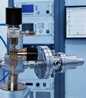 About RealMeter